8.4 Installing Peripheral Devices
This section describes the proper steps and precautions to take when installing or connecting various peripheral devices
to the drive.
Refer to peripheral device manual for detailed installation instructions.
NOTICE: Use a class 2 power supply (UL standard) when connecting to the control terminals. Improper application of peripheral devices
could result in drive performance degradation due to improper power supply.
u
Installing a Molded Case Circuit Breaker (MCCB) and Earth Leakage Circuit Breaker
(ELCB)
Install an MCCB or ELCB for line protection
between the power supply and the main circuit power supply input terminals
R/L1, S/L2 and T/L3. This protects the main circuit and devices wired to the main circuit while also providing overload
protection.
Consider the following when selecting and installing an MCCB or ELCB:
• The rated current of the MCCB or ELCB should be 1.5 to 2 times the rated output current of the drive. Use an MCCB
or ELCB with operation characteristics that do not trip the MCCB or ELCB faster than the drive overload protection
(shuts off the drive after 1 minute of operation at 150% of the drive rated current).
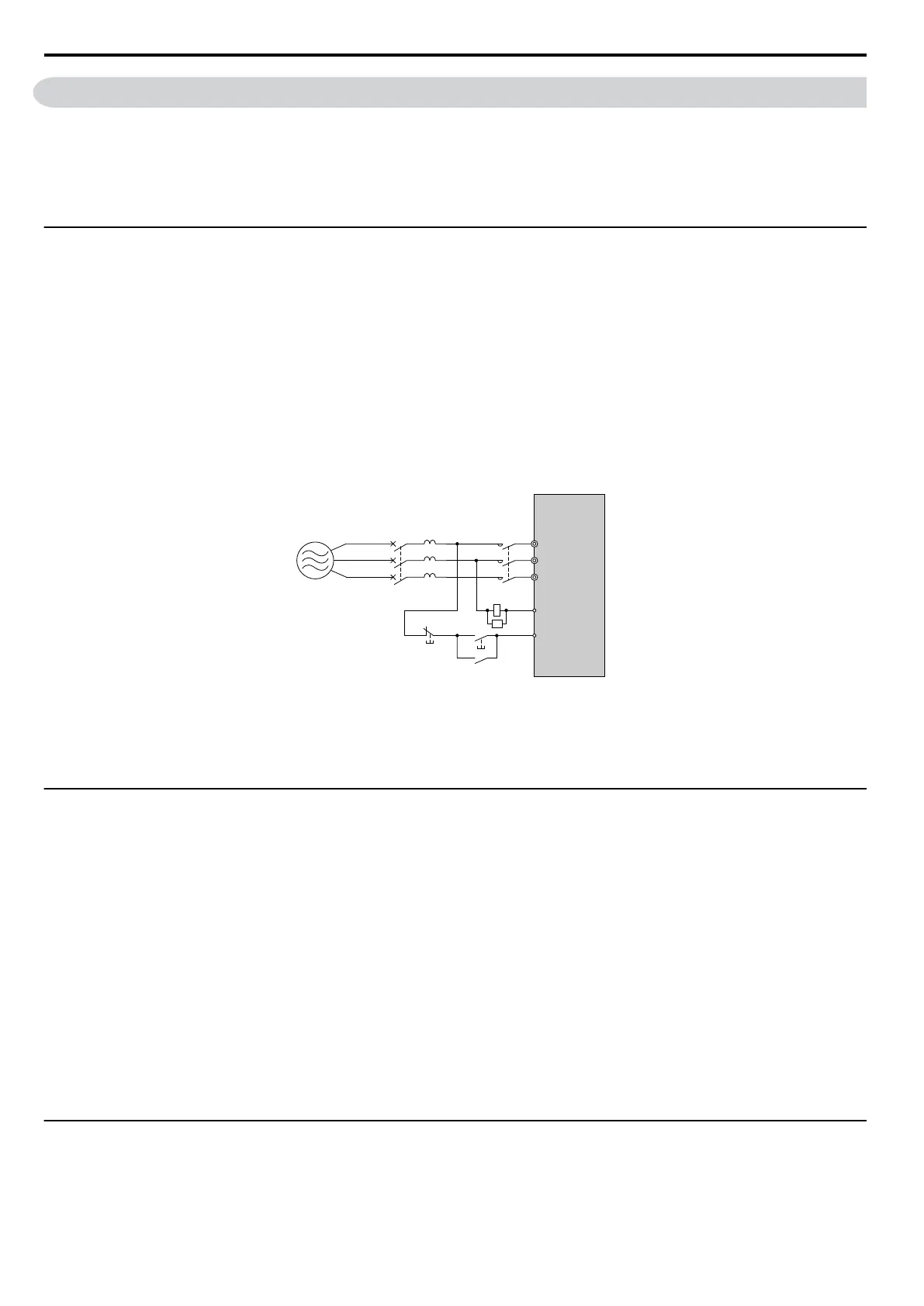
• If several drives are connected to one MCCB or an ELCB that is shared with other equipment, use a sequence that shuts
the power OFF when errors are output by using magnetic contactor (MC) as shown in the following figure.
Drive
Power
Supply
R/L1
MB
MCCB MC
MC
MC
MC
S/L2
T/L3
SA
Figure 8.2 Connecting an MCCB
WARNING! Electrical Shock Hazard. Disconnect the MCCB (or ELCB) and MC before wiring terminals. Failure to comply may result
in serious injury or death.
u
Installing a Leakage Breaker
Drive outputs generate high-frequency leakage current as a
result of high-speed switching. Install an Earth Leakage Circuit
Breaker (ELCB) on the input side of the drive to switch off potentially harmful leakage current. Because each drive
generates about 100 mA of leakage current across a 1 m cable and another 5 mA for each additional meter, each drive
should have a leakage breaker with a sensitivity amperage of at least 30 mA per drive to eliminate harmonic leakage current
and suppress any potentially harmful frequencies.
Refer to the Yaskawa catalog for ELCB selection. Leakage current can cause unprotected components to operate
incorrectly. If this is a problem, lower the carrier frequency, replace the components in question with parts protected against
harmonic current, or increase the sensitivity amperage of the leakage breaker to at least 200 mA per drive.
Factors in determining leakage current:
• Size of the AC drive
• AC drive carrier frequency
• Motor cable type and length
• EMI/RFI filter
To safely protect the drive system, select a breaker that senses AC and DC currents and high frequency currents.
u
Installing a Magnetic Contactor
n
Disconnecting the Power Supply
The
drive should be shut off in the
case of a fault in external equipment such as braking resistors through use of a Magnetic
Contactor (MC).
8.4 Installing Peripheral Devices
308
YASKAWA ELECTRIC SIEP C710606 16C YASKAWA AC Drive – V1000 Technical Manual

 Loading...


