5.8 L: Protection Functions
u
L1: Motor Protection Functions
n
L1-01: Motor Overload Protection Selection
The drive has an electronic overload protection function that estimates the motor overload level based on output current,
output
frequency, thermal motor characteristics, and time. An
oL1 fault will be triggered when motor overload is detected.
L1-01 sets the overload protection function characteristics according to the motor being used.
No. Name Setting Range Default
L1-01 Motor Overload Protection Selection
0 to 4; 6
<1>
A1-02 dependent
<1> Setting 6 is available in drive software versions PRG: 1016 and later.
Note: 1. When the motor protection function is enabled (L1-01 is not set to zero), an oL1 alarm can be output through one of the multi-
function outputs by setting H2-01 to 1F. The output will close when the motor overload level reaches 90% of the oL1 detection
level.
2. Select a method to protect the motor
from overheat by setting L1-01 to a value between 1 and 4; use setting 6 when running a single
motor from the drive. An external thermal relay is not required.
Setting 0: Disabled - Motor Overload Protection is not Provided
This setting should be used if no motor overheat protection is desired or if multiple motors are connected to one drive. In
this case it is recommended that you install a thermal relay for each motor as show in Figure 5.75
Drive
Power
supply
M1
MC1
MC1, MC2: Magnetic contactors
L10, L20: Thermal relays
L10
MC2 L20
M2
Figure 5.75 Example of Protection Circuit Design for Multiple Motors
NOTICE: Protect each motor with individual thermal overloads when multiple motors are connected to one drive. Failure to comply
could result in motor damage. Disable the electronic overload protection of the drive (L1-01 = “0: Disabled”) and protect each motor
with individual motor thermal overloads.
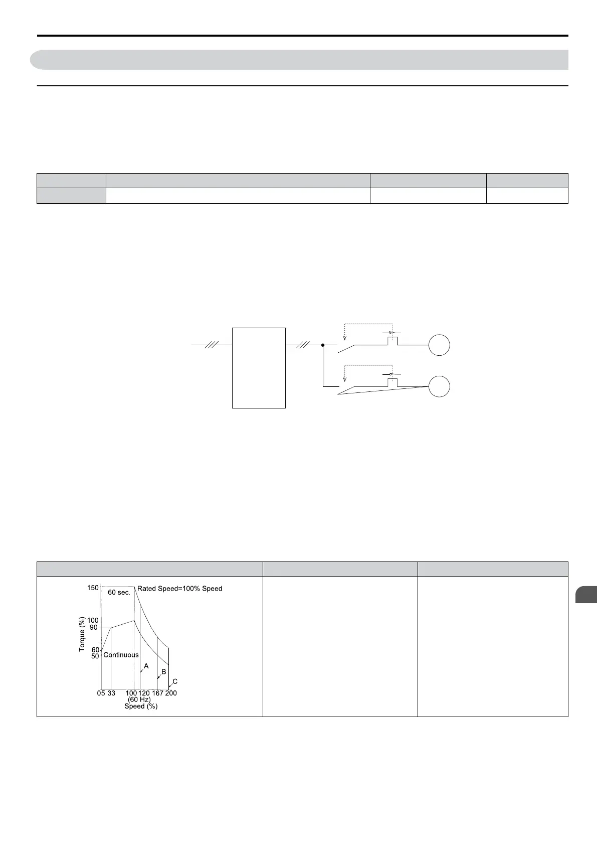
Setting 1: General Purpose Motor (standard self-cooled)
Because
the motor is self-cooled, the overload tolerance drops when the motor speed is lowered. The drive appropriately
adjusts the electrothermal trigger point according to the motor overload characteristics, protecting the motor from overheat
throughout the entire speed range.
Overload Tolerance Cooling Ability Overload Characteristics
Motor designed to operate from line
power.
Motor cooling is most effective when
running at rated nameplate base
frequency (check the motor
specifications).
Continuous operation at less than
line power frequency with 100%
load can trigger motor overload
protection (oL1). A fault is output
and the motor will coast to stop.
Setting 2: Drive Dedicated Motor (constant torque, 1:10)
Use this setting when operating a drive duty
motor with a torque ratio of 1:10. This motor type is allowed to run with 100%
load from 10% up to 100% speed. Running slower speeds with full load can trigger an overload fault.
5.8 L: Protection Functions
YASKAWA ELECTRIC SIEP C710606 16C YASKAWA AC Drive – V1000 Technical Manual
203
5
Parameter Details

 Loading...


