Set as a percentage of the maximum output frequency.
Note: The lower limits for the Jog frequency, multi-step speed settings, and 2-step speed settings do not change. When lower limits are set
to both the frequency reference (d2-02) and the
main frequency reference (d2-03), the drive uses the greater of those two values as the
lower limit.
No. Parameter Name Setting Range Default
d2-03 Master Speed Reference Lower Limit 0.0 to 110.0% 0.0%
u
d3: Jump Frequency
n
d3-01 to d3-04: Jump Frequencies 1, 2, 3, and Jump Frequency Width
In
order to avoid continuous operation at a
speed that causes resonance in driven machinery, the drive can be programmed
with three separate Jump frequencies that will not allow continued operation within specific frequency ranges. If the speed
reference falls within a Jump frequency dead band, the drive will clamp the frequency reference just below the dead band
and only accelerate past it when the frequency reference rises above the upper end of the dead band.
Setting parameters d3-01 through d3-03 to 0.0 Hz disables the Jump frequency function.
No. Parameter Name Setting Range Default
d3-01 Jump Frequency 1 0.0 to 400.0 Hz 0.0 Hz
d3-02 Jump Frequency 2 0.0 to 400.0 Hz 0.0 Hz
d3-03 Jump Frequency 3 0.0 to 400.0 Hz 0.0 Hz
d3-04 Jump Frequency Width 0.0 to 20.0 Hz 1.0 Hz
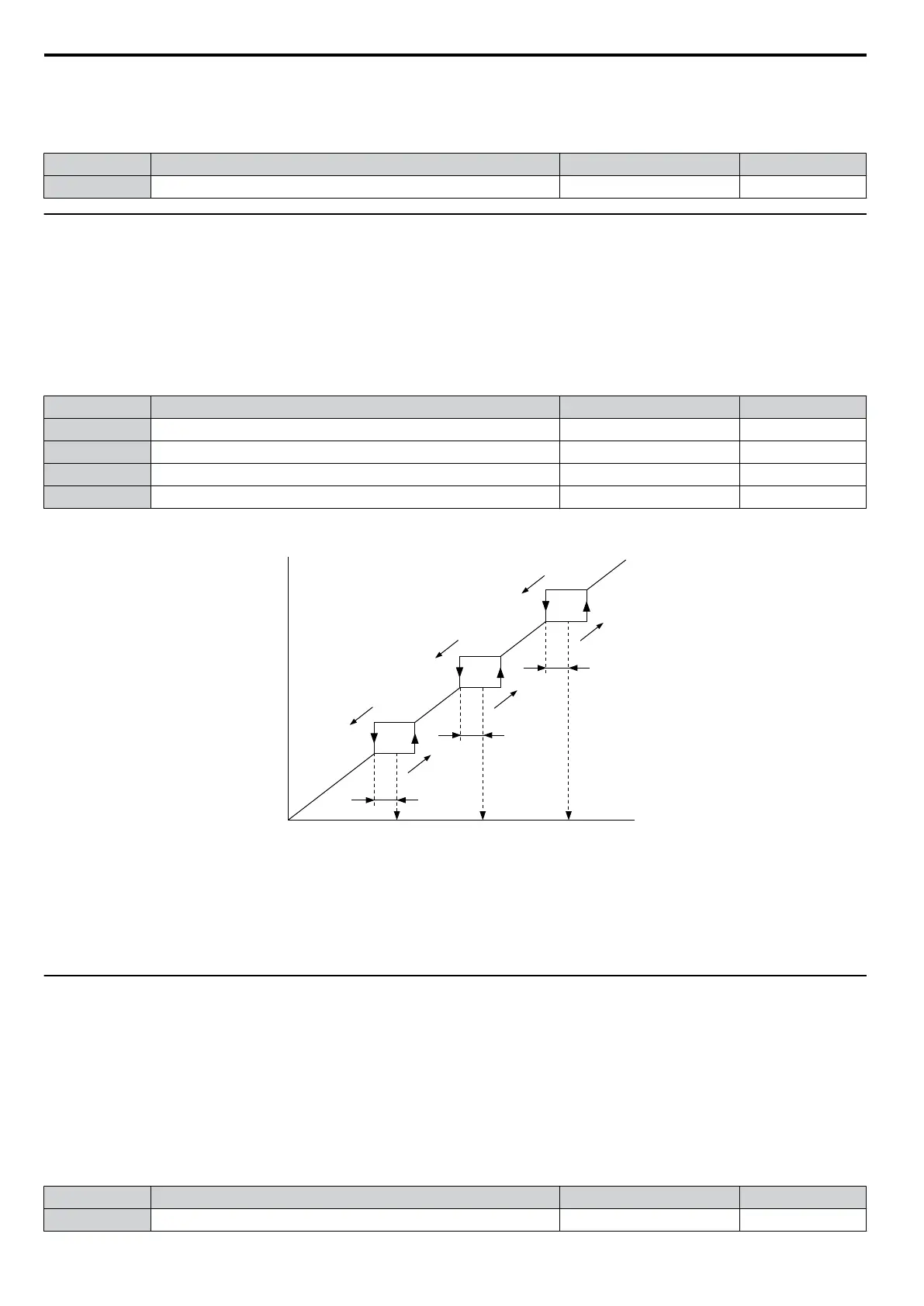
Figure 5.35 shows the relationship between the Jump frequency and the output frequency.
Output
frequency
Frequency
reference
Jump
Frequency
Width (d3-04)
Jump
Frequency 3
d3-03
Jump
Frequency 2
d3-02
Jump
Frequency 1
d3-01
Frequency
reference
decreases
Frequency
reference
increases
Jump
Frequency
Width (d3-04)
Jump
Frequency
Width (d3-04)
Figure 5.35 Jump Frequency Operation
Note: 1. The
drive
will
use
the
active
accel/decel
time
to pass through the specified dead band range but will not allow continuous operation
in that range.
2.
When using more than one Jump frequency, make sure that d3-01 ≥ d3-02 ≥ d3-03.
u
d4: Frequency Hold and Up/Down 2 Function
n
d4-01: Frequency Reference Hold Function Selection
This parameter is effective when either of the digital input functions listed below is used.
•
Accel/decel ramp hold function (H1-oo= A)
•
Up/Down function (H1-oo = 10 and 11, sets the frequency reference by digital inputs)
•
Up/Down 2 function (H1-oo = 75/76, adds a bias to the frequency reference using digital inputs)
Parameter
d4-01 determines whether the frequency reference or
the frequency bias (Up/Down 2) value is saved when the
Run command is cleared or the power supply is shut down.
No. Parameter Name Setting Range Default
d4-01 Frequency Reference Hold Function Selection 0 or 1 0
5.4 d: Reference Settings
156
YASKAWA ELECTRIC SIEP C710606 16C YASKAWA AC Drive – V1000 Technical Manual

 Loading...


