Attempted to use a function in the V/f motor control method that is only
possible in Open Loop Vector Control.
Check the motor control method and the functions available.
Simple V/f with PG was enabled while not in V/f Control (H6-01 = 3).
To use Simple V/f with PG, ensure the motor control method has been
set to V/f Control (A1-02 = “0”).
In Open Loop Vector Control, n2-02 is greater than n2-03 Correct parameter settings so that n2-02 is less than n2-03.
In Open Loop Vector Control, C4-02 is greater than C4-06 Correct parameter settings so that C4-02 is less than C4-06.
In PM Open Loop Vector Control, parameters E5-02 to E5-07 are set to
0.
• Set the correct motor code in accordance with the motor being used
(E5-01).
•
When using a special-purpose motor, set E5-oo in accordance with
the Test Report provided.
The following conditions are true in PM Open Loop Vector Control:
• E5-03 does not equal 0
• E5-09 and E5-24 are both equal to 0, or neither equals 0
• Set E5-09 or E5-24 to the correct value, and set the other to “0”.
• Set the motor-rated current for PM to “0” (E5-03).
Note: Use U1-18
to find which parameters are set outside the specified setting range. Other errors are given precedence over oPE08 when multiple
errors occur at the same time.
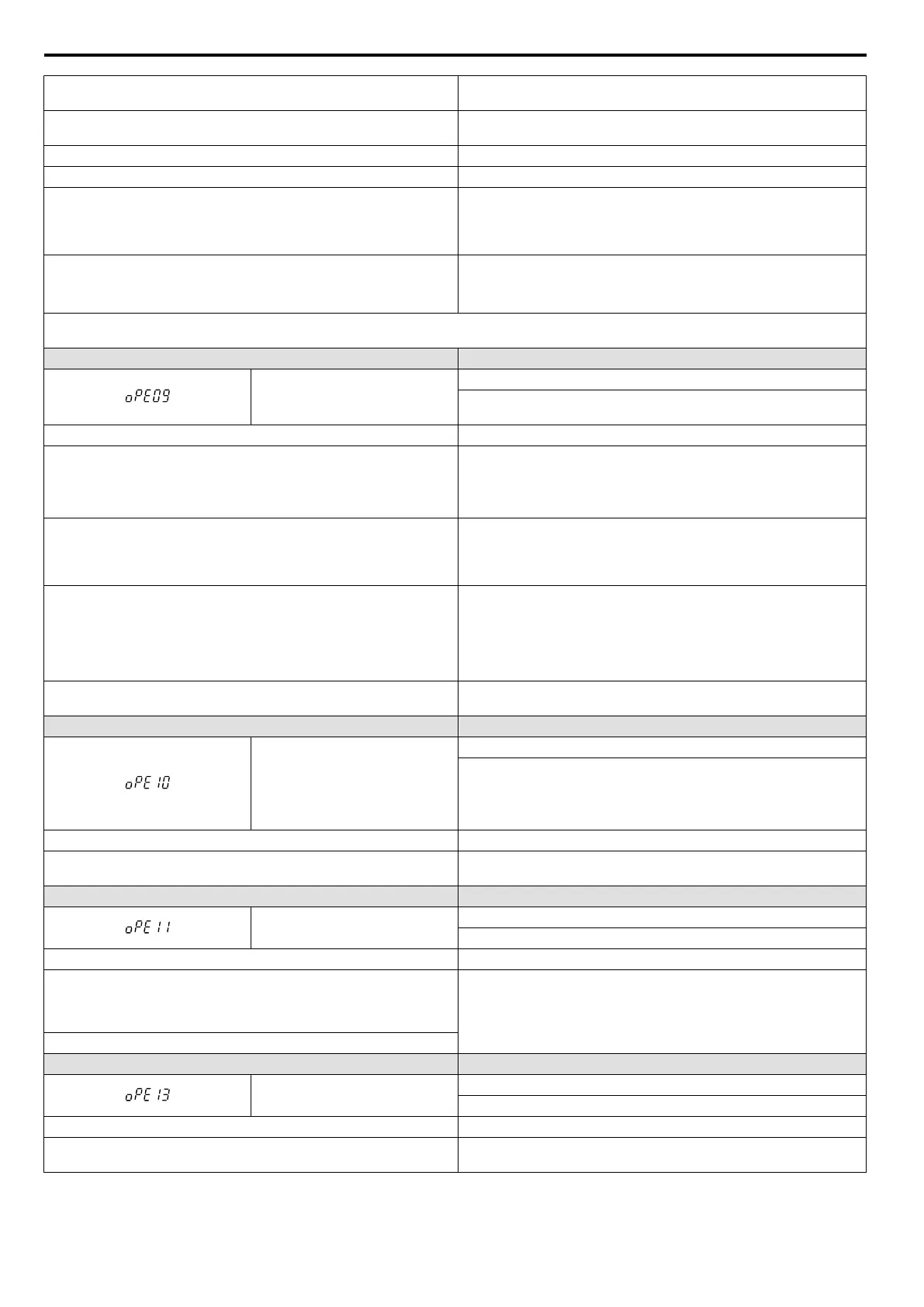
LED Operator Display Error Name
oPE09
PID Control Selection Fault
PID control function selection is incorrect. Requires that PID control is
enabled (b5-01 = 1 to 4).
Cause Possible Solutions
The following simultaneous contradictory settings:
• b5-15 not 0.0 (PID Sleep Function Operation Level)
• The stopping method is set to either DC injection braking or coast to
stop with a timer (b1-03 = 2 or 3).
• Set b5-15 to a value other than 0.
• Set the stopping method
to coast to stop or ramp to stop (b1-03 = 0 or
1).
• D control is being used on the setpoint deviation (b5-01 = 1) or on the
feedback value (b5-01 = 2).
• A negative PID output value is set to operate the drive in reverse (b5-11
= 1) and the frequency reference lower limit greater than 0 (d2-02 > 0).
Set parameters b5-01, b5-11, and d2-02 to the proper values.
• D control is being used on the setpoint deviation and the frequency
reference plus the PID output (b5-01 = 4), D control is being used on
the feedback value and the frequency reference plus the PID output
(b5-01 = 4).
• The frequency reference lower limit is set to a value greater than 0
(d2-02 > 0).
Set parameters b5-01 and d2-02 to the proper values.
The absolute value of the lower limit for PID output is greater than the PID
upper limit (b5-34 > b5-06).
Set parameters b5-34 and b5-06 to the proper values.
LED Operator Display Error Name
oPE10
V/f Data Setting Error
One or more of the parameters listed below are not set according to the
formula:
•
E1-09 ≤ E1-07 < E1-06 ≤ E1-11 ≤ E1-04
•
E3-09 ≤ E3-07 < E3-06 ≤ E3-11 ≤ E3-04
Cause Possible Solutions
V/f pattern setting error.
Correct the settings for E1-04, E1-06, E1-07, E1-09, and E1-11.
For motor 2, correct E3-04, E3-06, E3-07, E3-09, and E3-11.
LED Operator Display Error Name
oPE11
Carrier Frequency Setting Error
Correct the setting for the carrier frequency.
Cause Possible Solutions
The following simultaneous contradictory settings: C6-05 is greater than
6 and C6-04 is greater than C6-03 (carrier
frequency lower limit is greater
than the upper limit). If C6-05 is less than or equal to 6, the drive operates
at C6-03.
Correct the parameter settings.
Upper and lower limits between C6-02 and C6-05 contradict each other.
LED Operator Display Error Name
oPE13
Pulse Monitor Selection Error
Incorrect setting of monitor selection for Pulse Train (H6-06).
Cause Possible Solutions
Scaling for the Pulse Train monitor is set to 0 (H6-07 = 0) while H6-06 is
not set to 000, 031, 101, 102, 105, or 116.
Change scaling for the Pulse Train monitor or set H6-06 to 000, 031, 101,
102, 105, or 116.
6.6 Operator Programming Errors
276
YASKAWA ELECTRIC SIEP C710606 16C YASKAWA AC Drive – V1000 Technical Manual

 Loading...


