Settings for NC and NO input for the following functions were selected at
the same time:
• External Search Command 1 and External Search Command 2 (61 vs.
62)
• Fast-Stop N.O. and Fast-Stop N.C.
(15 vs. 17)
• KEB for Momentary Power Loss and High Slip Braking
(65, 66, 7A, 7B vs. 68)
• Motor Switch Command and Accel/Decel Time 2
(16 vs. 1A)
• KEB Command 1 and KEB Command 2
(65, 66 vs. 7A, 7B)
• FWD Run Command (or REV) and FWD/REV Run Command (2-wire)
(40, 41 vs. 42, 43)
• External DB Command and Drive Enable
(60 vs. 6A)
• Motor Switch Command and Up 2/Down 2 Command
(16 vs. 75, 76)
Check for contradictory settings assigned to the multi-function input
terminals at the same time. Correct setting errors.
One of the following settings was entered while H1-oo = 2 (External
Reference 1/2):
• b1-15 = 4 (Pulse Train Input) and H6-01 (Pulse Train Input Function
Selection) not = 0 (Frequency Reference)
• b1-15 or b1-16 set to 3 but no option card connected
• Although b1-15 = 1 (Analog Input) and H3-02 or H3-10 are set to 0
(Frequency Bias).
Correct the settings for the multi-function input terminal parameters.
H2-oo
= 38 (Drive
Enabled) but H1-oo is not set to 6A (Drive Enable).
H1-oo = 7E (Direction Detection)
although H6-01 is not set to 3 (Simple
V/f with PG).
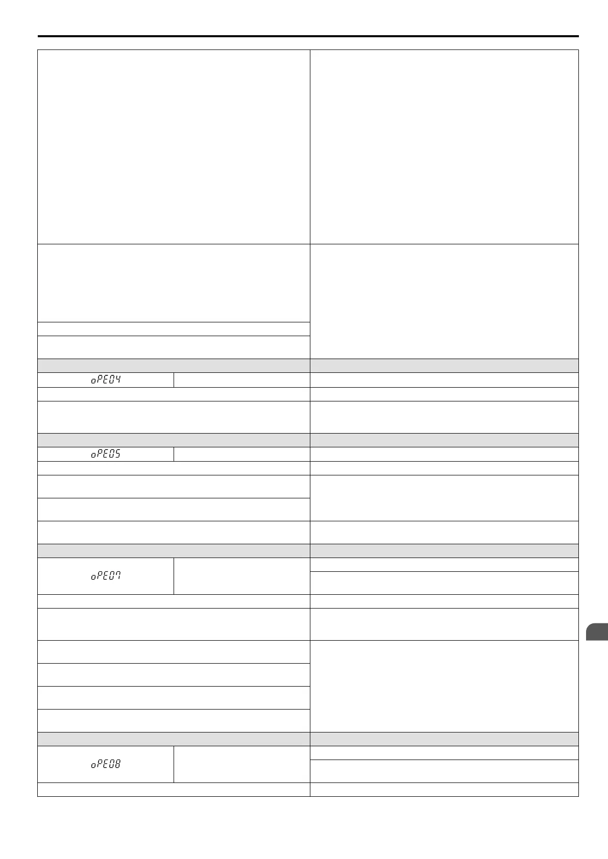
LED Operator Display Error Name
oPE04 Initialization required.
Cause Possible Solutions
The drive, control board, or terminal board has been replaced and the
parameter settings between the control board and the terminal board no
longer match.
To load the parameter settings to the drive that are stored in the terminal
board, set A1-03 to 5550. Initialize parameters after drive replacement
by setting A1-03 to 1110 or 2220.
LED Operator Display Error Name
oPE05 Run Command/Frequency Reference Source Selection Error
Cause Possible Solutions
Frequency reference is assigned to an option card (b1-01 = 3) that is not
connected to the drive.
Reconnect the option card to the drive.
The Run command is assigned to an option card (b1-02 = 3) that is not
connected to the drive.
Frequency reference is assigned to the pulse train input (b1-01 = 4), but
terminal RP is not set for pulse train input (H6-01 > 0)
Set H6-01 to “0”.
LED Operator Display Error Name
oPE07
Multi-Function Analog Input Selection Error
A contradictory setting is assigned to multi-function analog inputs H3-02
through to H3-10 and PID functions conflict.
Cause Possible Solutions
H3-02 and H3-10 are set to the same value.
Change the settings to H3-02 and H3-10 so that functions no longer
conflict. Note: Both 0 (primary analog frequency reference) and F (Not
Used) can be set to H3-02 and H3-10 at the same time.
The following simultaneous contradictory settings: H3-02 or H3-10 = B
(PID Feedback) H6-01 (Pulse Train Input) = 1 (PID Feedback)
Disable one of the PID selections.
The following simultaneous contradictory settings: H3-02 or H3-10 = C
(PID Target Value) H6-01 = 2 (pulse train
input sets the PID target value)
The following simultaneous contradictory settings: H3-02 or H3-10 = C
(PID Target Value) b5-18 = 1 (enables b5-19 as the target PID value)
The following simultaneous contradictory settings: H6-01 or H3-10 = C
(PID Target Value) b5-18 = 1 (enables b5-19 as the target PID value)
LED Operator Display Error Name
oPE08
Parameter Selection Error
A function has been set that cannot be used in the motor control method
selected.
Cause Possible Solutions
6.6 Operator Programming Errors
YASKAWA ELECTRIC SIEP C710606 16C YASKAWA AC Drive – V1000 Technical Manual
275
6
Troubleshooting

 Loading...


