10 V5 V
0 V
Gain = 200 %
100 %
Frequecny
reference
Bias = 0 %
E1-04
Figure 5.70 Frequency Reference Setting by Analog Input with Increased Gain
• Bias H3-04 = -25%, A1 as frequency reference input
An input of 0 Vdc will be equivalent to a -25% frequency reference.
When parameter H3-01 = 0 the minimum frequency reference is 0% between 0 and 2.5 Vdc input. An analog input of
2.5 to 10 Vdc will now be the same as 0 to 100% of the frequency reference span.
When parameter H3-01 = 1, the motor will rotate in reverse between 0 and 2.5 Vdc input.
2.0 V
0
10 V
Gain = 100 %
Frequency
reference
Bias = -25%
H3-01 = 0
H3-01 = 1
Figure 5.71 Frequency Reference Setting by Analog Input with Negative Bias
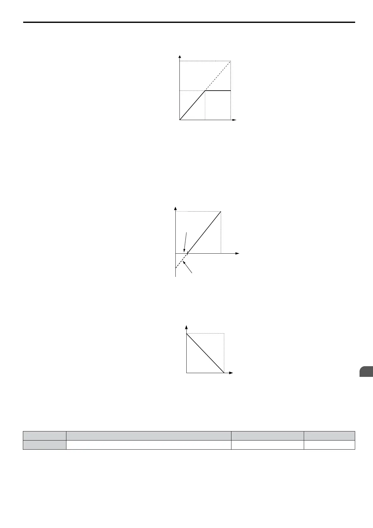
• Gain = 0%, Bias = 100%, A1 as frequency reference input
This setting leads to an inverse-acting frequency reference. The minimum analog input level (0 Vdc) will produce a
100% frequency reference and the maximum analog input level (10 Vdc) will produce a 0% frequency reference.
0 V 10 V
Gain = 0 %
Bias = 100 %
Frequency
reference
Figure 5.72 Frequency Reference Setting by Analog Input with Inverse Gain and Bias Settings
n
H3-09: Terminal A2 Signal Level Selection
Selects
the input signal level for analog input
A2. Be sure to also set DIP switch S1 on the terminal board accordingly for
a voltage input or current input.
No. Name Setting Range Default
H3-09 Terminal A2 Signal Level Selection 0 to 3 2
Setting 0: 0 to 10 Vdc with Lower Limit
The input level is 0 to 10 Vdc. Negative input values will be limited to 0. Refer to the explanation of H3-01, Setting 0.
Refer to Setting 0: 0 to 10 Vdc with Limit on page 195
5.7 H: Terminal Functions
YASKAWA ELECTRIC SIEP C710606 16C YASKAWA AC Drive – V1000 Technical Manual
197
5
Parameter Details

 Loading...


