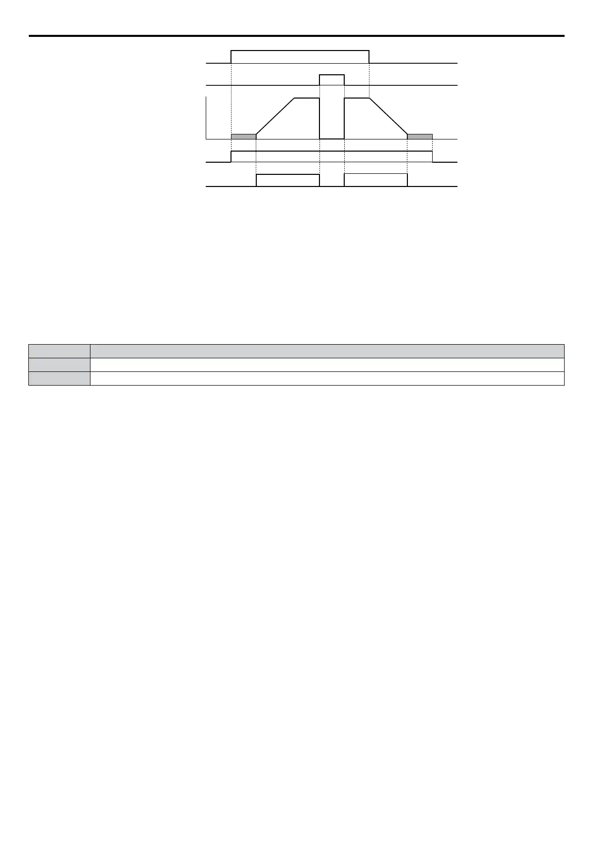
ON
ON
OFF
OFF
ONOFF
ON
run command
baseblock
command
output
frequency
during run
during frequency
output
OFF
Figure 5.66 During Frequency Output Time Chart
Setting 38: Drive Enabled
A Drive Enable digital output will reflect the status of a digital input configured as a Drive Enable input (H1-oo = 6A).
If the Drive Enable digital input is closed then the Drive Enabled digital output will also close.
Setting 39: Watt Hour Pulse Output
Outputs a pulse to indicate the watt hours. Refer to H2-06: Watt Hour Output Unit Selection on page 195 for details.
Setting 3C: LOCAL/REMOTE Status
Output terminal closes while the drive is set for LOCAL and opens when in REMOTE.
Status Description
Open REMOTE: The selected external reference (b1-01/b1-02 or b1-15/b1-16) is used as frequency reference and Run command source
Closed LOCAL: The digital operator is used as frequency reference and Run command source
Setting 3D: During Speed Search
Output terminal closes while Speed Search is being
performed. Refer to b3: Speed Search on page 125 for details on the
Speed Search function.
Setting 3E: PID Feedback Low
Output terminal closes when a PID feedback loss is detected. The feedback is considered to be lost if it falls below the
level set to b5-13 for longer than the time set to b5-14. Refer to PID Feedback Loss Detection on page 135 for details.
Setting 3F: PID Feedback High
Output terminal closes when a PID feedback loss is detected. The feedback is considered to be lost if it rises beyond the
level set to b5-36 for longer than the time set to b5-37. Refer to PID Feedback Loss Detection on page 135 for details.
Setting 4A: During KEB Operation
Output terminal closes while KEB is being performed. Refer to Kinetic Energy Backup (KEB) Function on page 208
for a KEB function description.
Setting 4B: During Short Circuit Braking
Closes the output terminal while Short Circuit Braking is being executed.
Setting 4C: During Fast-stop
Output terminal closes when a Fast-stop is being executed. C1-09: Fast-stop Time for details.
Setting 4D: oH Pre-Alarm Time Limit
Output terminal closes when the drive is reducing the speed due to a drive overheat alarm (L8-03 = 4) and the overheat
alarm has not disappeared after ten frequency reduction operation cycles. Refer to L8-03: Overheat Pre-Alarm Operation
Selection on page 224 for details.
Setting 4E: Braking Transistor Fault (rr)
The output closes when the internal braking transistor reaches the overheat level.
Setting 4F: Braking Resistor Overheat (rH)
The output closes when the braking resistor exceeds the overheat level. the braking resistor may overheat due to the motor
regeneration or short deceleration time setting.
Setting 90 to 92: DriveWorksEZ Digital Output 1 to 3
These settings are for digital output functions used in DriveWorksEZ. Normally there is no need to change or apply these
settings.
5.7 H: Terminal Functions
194
YASKAWA ELECTRIC SIEP C710606 16C YASKAWA AC Drive – V1000 Technical Manual

 Loading...


