Switching Accel/decel Times by a Frequency Level
The drive can automatically switch from accel/decel times
4 (C1-07 and C1-08) to the default accel/decel times (C1-01/02
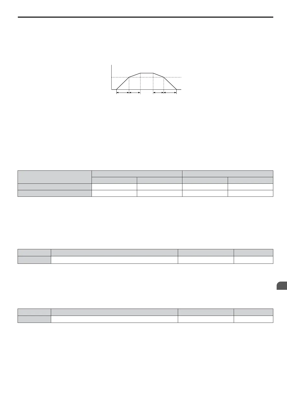
for motor 1, C1-05/06 for motor 2) when the output frequency exceeds the frequency level set in parameter C1-11. When
it falls below this level, the accel/decel times are switched back. Figure 5.23 shows an operation example.
Note: Acceleration and deceleration times selected by digital inputs have priority over the automatic switching by a frequency level. For
example, if accel/decel time 2 is selected, the drive will use this time only and not switch from accel/decel time 4 to the selected one.
Output Frequency
C1-11
Accel/Decel Time
Switch Frequency
C1-07
setting
When the output frequency C1-11, drive uses Accel/De
cel Time 1 (C1-01, -02)
When the output frequency < C1-11, drive uses Accel/Decel Time 2 (C1-07, -08)
C1-01
setting
C1-02
setting
C1-08
setting
Figure 5.23 Accel/Decel Time Switching Frequency
Switching Acceleration and Deceleration Times by Motor Selection
When switching between motor 1 and 2 using a digital input (H1-oo = 16) parameters C1-01 to C1-04 become accel/
decel time 1/2 for motor 1 and C1-05 to C1-08 become accel/decel time 1/2 for motor 2. In this case the digital input
“Accel/Decel Time 2 Selection” can not be used (this would trigger an oPE03 error, indicating a contradictory multi-
function input settings).
Table 5.10 explains the activation of accel/decel times depending on the motor selection and accel/decel time selection.
Table 5.10 Motor Switching and Accel/Decel Time Combinations
Accel/Decel Time 1 (H1-oo = 7)
Motor 1 Selected Motor 2 Selected
Accel Decel Accel Decel
Open C1-01 C1-02 C1-05 C1-06
Closed C1-03 C1-04 C1-07 C1-08
n
C1-09: Fast-stop Time
Parameter
C1-09 will set a special deceleration that
is used when certain faults occur or that can be operated by closing a
digital input configured as H1-oo = 15 (N.O. input) or H1-oo = 17 (N.C. input). The input does not have to be closed
continuously, even a momentary closure will trigger the Fast-stop operation.
Unlike standard deceleration, once the Fast-stop operation is initiated, the drive cannot be restarted until the deceleration
is complete, the Fast-stop input is cleared, and the Run command is cycled.
A digital output programmed for “During Fast-stop” (H2-01/02/03 = 4C) will be closed as long as Fast-stop is active.
No. Parameter Name Setting Range Default
C1-09 Fast-stop Time
0.0 to 6000.0 s
<1>
10.0 s
<1> The setting range for the acceleration and deceleration times is determined by C1-10 (Accel/Decel Time Setting Units). For example, if the
time is set in units of 0.01 s (C1-10 = 0), the setting range becomes 0.00 to 600.00 s
NOTICE: Rapid deceleration can trigger an overvoltage fault. When
faulted, the drive output shuts off, and the motor coasts. To avoid
this uncontrolled motor state and to ensure that the motor stops quickly and safely, set an appropriate Fast-stop time to C1-09.
n
C1-10: Accel/Decel Time Setting Units
Determines the units for the acceleration and deceleration times set to C1-01 through C1-09 using parameter C1-10.
No. Parameter Name Setting Range Default
C1-10 Accel/Decel Time Setting Units 0 or 1 1
Setting 0: 0.01 s Units
The
accel/decel.
times
are
set
in
0.01
s
units. The setting range will be 0.00 to 600.00 s. If any of the parameters C1-01 to
C1-09 is set to 600.1 seconds or more, then C1-10 cannot be set to 0.
Setting 1: 0.1 s Units
The accel/decel. times are set in 0.1 s units. The setting range will be 0.0 to 6000.0 s.
5.3 C: Tuning
YASKAWA ELECTRIC SIEP C710606 16C YASKAWA AC Drive – V1000 Technical Manual
143
5
Parameter Details

 Loading...


