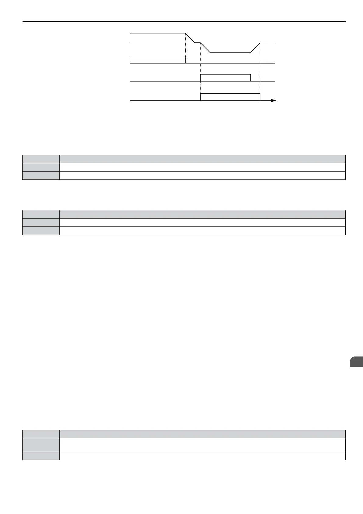
Output frequency
time
FWD Run command
REV Run command
During Reverse
OFF
ON
Figure 5.65 Reverse Direction Output Example Time Chart
Setting 1B: During Baseblock (N.C.)
Output opens to indicate that the drive is in a baseblock state. While Baseblock is executed, output transistors are not
switched and no voltage is output.
Status Description
Open Baseblock is being executed.
Closed Drive is not in a baseblock state.
Setting 1C: Motor 2 Selected
This output function shows the motor 1/2 selection
status. Refer to Setting 16: Motor 2 Selection on page 181 for details
on switching motors.
Status Description
Open Motor 1 is selected.
Closed Motor 2 is selected.
Setting 1E: Restart Enabled
The Restart Enabled output will be closed once the fault restart function becomes active and will remain closed until a
successful restart is accomplished or the number of
Auto Restart attempts as specified by L5-01 is reached. Refer to L5:
Fault Restart on page 220 for details on automatic fault restart.
Setting 1F: Motor Overload Alarm oL1
An output programmed for this function will be closed when the motor overload level estimated by the oL1 fault detection
exceeds 90% of the oL1 detection level. Refer to L1-01: Motor Overload Protection Selection on page 203 for details.
Setting 20: Drive Overheat Pre-alarm (oH)
Output closes whenever the drive heatsink temperature reaches the level specified by parameter L8-02. Refer to L8-02:
Overheat Alarm Level on page 224 for details on drive overheat detection.
Setting 22: Mechanical Weakening Detection
Output closes when mechanical weakening is detected. Refer to Mechanical Weakening Detection on page 222 for
details.
Setting 2F: Maintenance Period
The output closes when the cooling fan, DC bus capacitors, or DC bus pre-charge relay may require maintenance as
determined by the estimated performance life span of those components.
Setting 30: During Torque Limit
Output closes when the motor is operating at the torque limit specified by the L7-oo parameters or an analog input. This
setting is only valid when using Open Loop Vector Control (A1-02 = 2). Refer to L7-01/02/03/04: Torque Limits on
page 223 for details.
Setting 37: During Frequency Output
Output closes when the drive is outputting a frequency.
Status Description
Open
Drive is not outputting a frequency. One of the following functions is being performed: Stop, baseblock, DC injection braking
(during initial excitation), short circuit braking.
Closed Drive is outputting frequency.
5.7 H: Terminal Functions
YASKAWA ELECTRIC SIEP C710606 16C YASKAWA AC Drive – V1000 Technical Manual
193
5
Parameter Details

 Loading...


