• Short Circuit Braking at stop in PM OLV control.
No. Name Setting Range Default
b2-01 DC Injection Braking Start Frequency 0.0 to 10.0 Hz 0.5 Hz
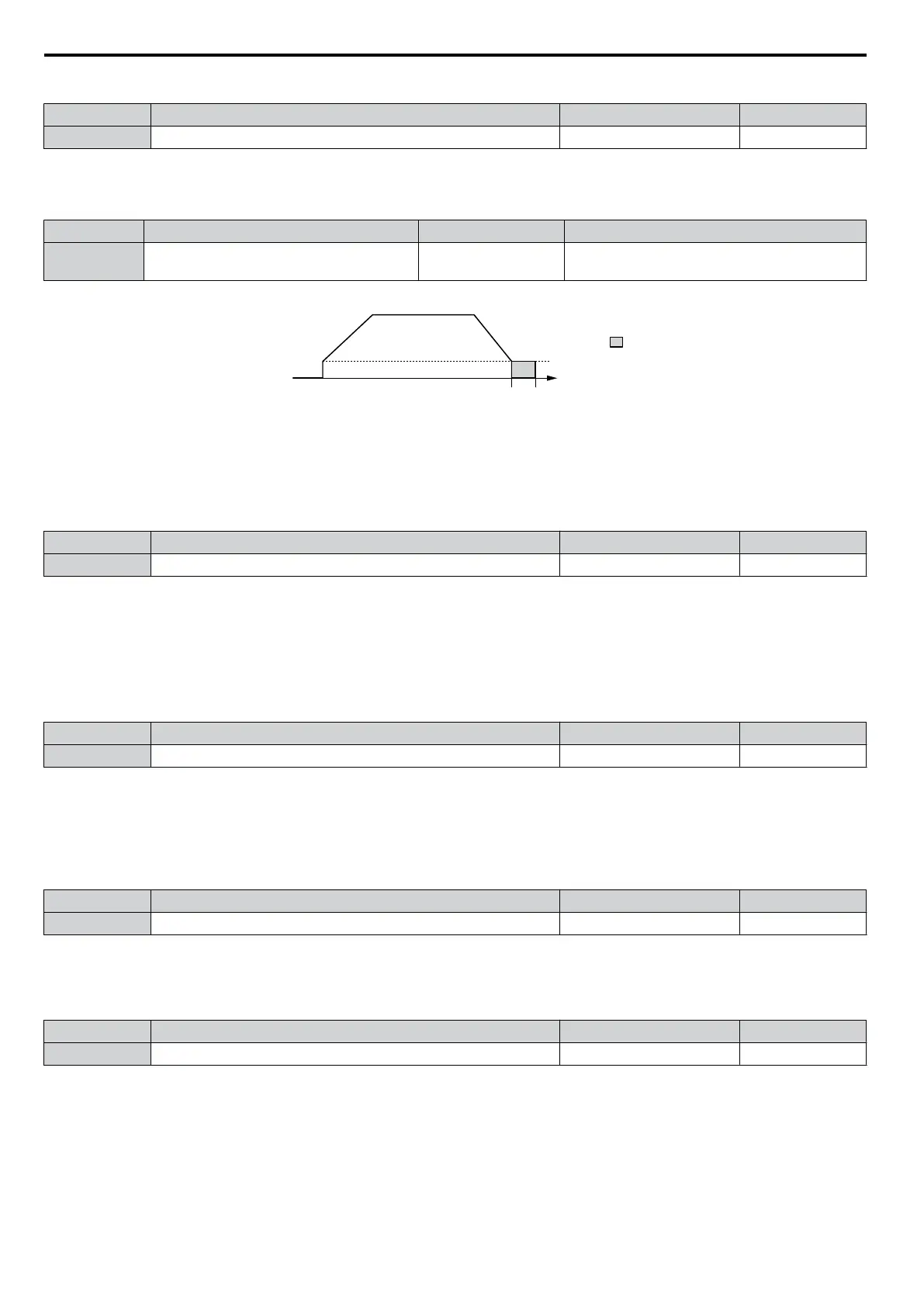
When the output frequency while ramping to stop drops below b2-01, the drive begins DC Injection/Short Circuit Braking
in order to completely stop the motor at
the end of deceleration. If b2-01 < E1-09 (Minimum Frequency), then DC Injection/
Short Circuit Braking begins at the frequency set to E1-09.
No. Name Setting Range Default
E1-09 Minimum Output Frequency
0.0 to 400.0 Hz
<1>
Determined by A1-02 and E1-03 and on E5-01
in OLV for PM.
<1> The upper limit for the setting range is determined by E1-04.
b2-04
b2-01
DC Injection Braking
start frequency
output
frequency
braking time
Figure 5.10 DC Injection Braking during Deceleration
n
b2-02: DC Injection Braking Current
Sets the DC Injection Braking current as a percentage of the drive rated current. If set to larger than 50%, the carrier
frequency is automatically reduced to 1 kHz.
No. Name Setting Range Default
b2-02 DC Injection Braking Current 0 to 75% 50%
The level of DC Injection Braking current affects the strength of the magnetic field attempting to lock the motor shaft.
Increasing
the
current
level
will
increase
the
amount
of heat generated by the motor windings. This parameter should only
be increased to the level necessary to hold the motor shaft.
n
b2-03: DC Injection Braking Time at Start
Sets the time of DC Injection Braking at start. It can be used to stop a coasting motor before restarting it or to apply a
braking torque at start. Disabled when set to 0.00 s.
No. Name Setting Range Default
b2-03 DC Injection Braking Time at Start 0.00 to 10.00 s 0.50 s
Note: Before starting an uncontrolled rotating motor (e.g. a fan motor driven by windmill effect), DC Injection or Speed Search should be
used to either stop the motor or detect its speed before starting it. Otherwise motor stalling and other faults can occur.
n
b2-04: DC Injection Braking Time at Stop
This
parameter works in combination with b2-01, and
sets the DC Injection Braking time at stop. Used to completely stop
a motor with high inertia load after ramp down. Increase the setting if the motor tends to coast by inertia after a stop.
No. Name Setting Range Default
b2-04 DC Injection Braking Time at Stop 0.00 to 10.00 s 0.50 s
n
b2-08: Magnetic Flux Compensation Value
Sets
the magnetic flux compensation as a percentage of the no-load current value (E2-03) and can be used to increase the
motor flux when the motor is started up.
No. Name Setting Range Default
b2-08 Magnetic Flux Compensation Value 0 to 1000% 0%
This parameter allows the magnetizing motor flux to be boosted when starting the motor and thereby facilitate a quick
ramp-up of the torque reference and magnetizing current reference in order to reduce motor slip during start. This flux
level
will
be
applied
below
the
minimum
output
frequency set to E1-09 until the DC Injection time at start (b2-03) expires.
It may be used to compensate for reduced starting torque due to motor circuit inefficiencies.
n
b2-12: Short Circuit Brake Time at Start
Short-Circuit braking can be used in Open Loop Vector for PM motors. By shorting all three motor phases it produces a
braking torque in the motor and can be used to stop a coasting motor before starting it.
Parameter b2-12 sets the time for Short-Circuit Brake operation at start. Disabled when set to 0.00 s.
5.2 b: Application
124
YASKAWA ELECTRIC SIEP C710606 16C YASKAWA AC Drive – V1000 Technical Manual

 Loading...


