Setting 3 to 5: Multi-Step Speed Reference 1 to 3
Used to switch Multi-Step Speed frequency references d1-01
to d1-08 by digital inputs. Refer to d1-01 to d1-17: Frequency
Reference 1 to 16 and Jog Reference on page 154 for details.
Setting 6: Jog Frequency Reference Selection
Used to select the Jog frequency set in parameter d1-17 as active frequency reference. Refer to d1-01 to d1-17: Frequency
Reference 1 to 16 and Jog Reference on page 154 for details.
Setting 7: Accel/Decel Time Selection 1
Used to switch between accel/decel times 1 and 2. Refer to C1-01 to C1-08: Accel/Decel Times 1 to 4 on page 142 for
details.
Setting 8/9: External Baseblock (N.O.) and External Baseblock (N.C.)
Setting 8 or 9 assign the Baseblock command to digital input terminals. When the drive receives a Baseblock command,
the output transistor stop switching and the motor coasts to stop. During this time, the alarm “bb” will flash on the LED
operator to indicate baseblock. For more information on alarms, Refer to Alarm Detection on page 266. When baseblock
ends and a Run command is active, the drive performs Speed Search to get the motor running again (Refer to b3: Speed
Search on page 125 for details).
Operation
Inputs
Setting 8 (N.O.) Setting 9 (N.C.)
Normal operation Open Closed
Baseblock (Interrupt output) Closed Open
NOTICE: If using baseblock in hoist applications, make sure the brake closes when the drive output is cut off by a Baseblock input.
Failure to do so will result in the motor suddenly coasting when the Baseblock command is entered, causing the load to slip.
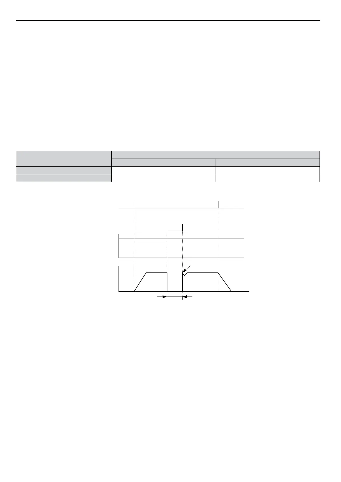
Begin Speed Search from the
previous frequency reference
Run command
Baseblock input
Frequency
reference
Output frequency
OFF ON
Output off, motor coasts
ON
Baseblock
release
Figure 5.47 Baseblock Operation During Run
Setting A: Accel/Decel Ramp Hold
When the digital input programmed for the Accel/Decel
Ramp Hold function closes, the drive will lock ("hold") the output
frequency. All acceleration or deceleration will cease, and the drive will hold the current speed. Acceleration or deceleration
will resume once the input is opened again.
If the Accel/Decel Ramp Hold function is enabled (d4-01 = 1), the drive will save the output frequency to memory whenever
the Ramp Hold input is closed. When the drive is restarted after stop or after power supply interruption, the output frequency
that was saved will become the frequency reference (provided that the Accel/Decel Ramp Hold input is still closed). Refer
to d4-01: Frequency Reference Hold Function Selection on page 156 for details.
Setting B: Drive Overheat Alarm (oH2)
Triggers an oH2 alarm when the contact closes. Because this is an alarm, drive operation is not affected.
Setting C: Analog Inputs A1/A2 Enable
If a digital input programmed for this function is open, both analog inputs A1 and A2 are disabled. Close the input to
enable the inputs.
The drive disregards the input value selected by parameter H3-14 when this terminal closes.
Note: In drive software versions PRG: 1015 and earlier, input values to terminals A1 and A2 are both disregarded when this terminal closes.
5.7 H: Terminal Functions
178
YASKAWA ELECTRIC SIEP C710606 16C YASKAWA AC Drive – V1000 Technical Manual

 Loading...


