LED Operator Display Fault Name
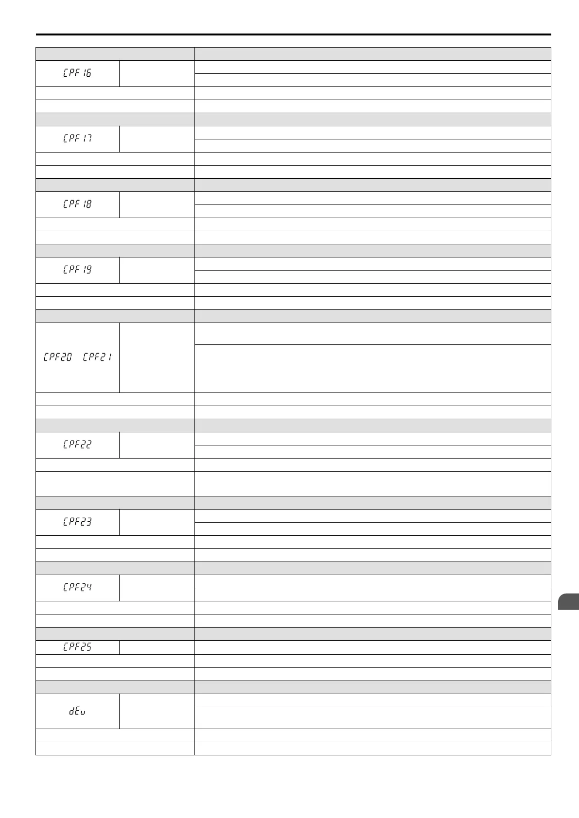
CPF16
Clock Fault
Standard clock error.
Cause Possible Solution
Hardware is damaged. Replace the drive.
LED Operator Display Fault Name
CPF17
Timing Fault
A timing error occurred during an internal process.
Cause Possible Solution
Hardware is damaged. Replace the drive.
LED Operator Display Fault Name
CPF18
Control Circuit Fault
CPU error. Non-Maskable Interrupt (An unusual interrupt was triggered by noise, etc.)
Cause Possible Solution
Hardware is damaged. Replace the drive.
LED Operator Display Fault Name
CPF19
Control Circuit Fault
CPU error (Manual reset due to noise, etc.)
Cause Possible Solution
Hardware is damaged. Replace the drive.
LED Operator Display Fault Name
or
CPF20 or CPF21
One of the following faults occurred: RAM fault, FLASH memory error, watchdog circuit exception,
clock error
• RAM fault.
• FLASH memory error (ROM error).
• Watchdog circuit exception (self-diagnostic error).
• Clock error.
Cause Possible Solution
Hardware is damaged. Replace the drive.
LED Operator Display Fault Name
CPF22
A/D Conversion Fault
A/D conversion error.
Cause Possible Solution
Control circuit is damaged.
• Cycle power to the drive. Refer to Diagnosing and Resetting Faults on page 279.
• If the problem continues, replace the drive.
LED Operator Display Fault Name
CPF23
PWM Feedback Fault
PWM feedback error.
Cause Possible Solution
Hardware is damaged. Replace the drive.
LED Operator Display Fault Name
CPF24
Drive Capacity Signal Fault
Entered a capacity that does not exist. (Checked when the drive is powered up.)
Cause Possible Solution
Hardware is damaged. Replace the drive.
LED Operator Display Fault Name
CPF25 Terminal Board Not Connected
Cause Possible Solution
Terminal board is not connected correctly. Reconnect the terminal board to the connector on the drive, then cycle the power to the drive.
LED Operator Display Fault Name
dEv
Speed Deviation (for Simple V/f with PG)
According to the pulse input (RP), the speed deviation is greater than the setting in F1-10 for longer
than the time set to F1-11.
Cause Possible Solution
Load is too heavy. Reduce the load.
6.4 Fault Detection
YASKAWA ELECTRIC SIEP C710606 16C YASKAWA AC Drive – V1000 Technical Manual
255
6
Troubleshooting

 Loading...


