Speed Search related parameters are not set
to the proper values.
• Check values set to Speed Search related parameters.
• Adjust the Speed Search current and Speed Search deceleration times (b3-02 and b3-03
respectively).
• After Auto-Tuning, enable Speed Estimation Type Search (b3-24 = “1”).
Output current fluctuation due to input phase
loss
Check the power supply for phase loss.
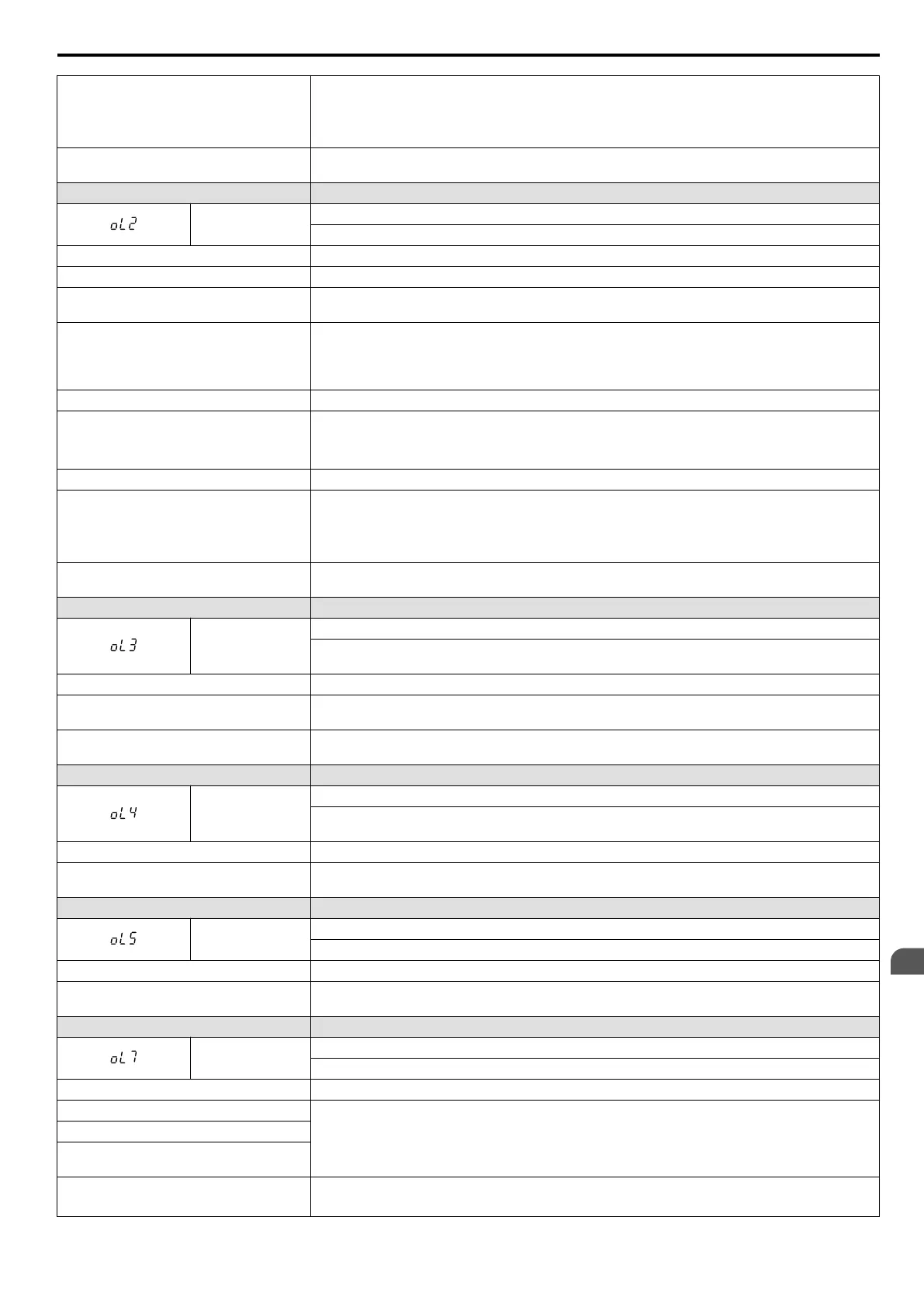
LED Operator Display Fault Name
oL2
Drive Overload
The thermal sensor of the drive triggered overload protection.
Cause Possible Solution
Load is too heavy. Reduce the load.
Cycle times are too short during acceleration
and deceleration.
Increase the settings for the acceleration and deceleration times (C1-01 through C1-08).
Voltage is too high for the V/f characteristics.
• Adjust the preset V/f pattern (E1-04 through E1-10). This will mainly involve reducing E1-08 and
E1-10.
• Be careful not to lower E1-08 and E1-10 excessively because this reduces load tolerance at low
speeds.
Drive capacity is too small. Replace the drive with a larger model.
Overload occurred when operating at low
speeds.
• Reduce the load when operating at low speeds.
• Replace the drive with a model that is one frame size larger.
• Lower the carrier frequency (C6-02).
Excessive torque compensation. Reduce the torque compensation gain (C4-01) until there is no speed loss but less current.
Speed Search related parameters are not set
correctly.
• Check the settings for all Speed Search related parameters.
• Adjust the current used during Speed Search and the Speed Search deceleration time (b3-03 and
b3-02 respectively).
• After Auto-Tuning the drive, enable the Speed Search Estimation Type (b3-24 = “1”).
Output current fluctuation due to input phase
loss
Check the power supply for phase loss.
LED Operator Display Fault Name
oL3
Overtorque Detection 1
The current has exceeded the value set for torque detection (L6-02) for longer than the allowable time
(L6-03).
Cause Possible Solution
Parameter settings are not appropriate for the
type of load.
Check the settings of parameters L6-02 and L6-03.
There is a fault on the machine side (e.g., the
machine is locked up).
Check the status of the load. Remove the cause of the fault.
LED Operator Display Fault Name
oL4
Overtorque Detection 2
The current has exceeded the value set for Overtorque Detection 2 (L6-05) for longer than the allowable
time (L6-06).
Cause Possible Solution
Parameter settings are not appropriate for the
type of load.
Check the settings of parameters L6-05 and L6-06.
LED Operator Display Fault Name
oL5
Mechanical Weakening Detection 1
Overtorque occurred, matching the conditions specified in L6-08.
Cause Possible Solution
Overtorque occurred, triggering the
mechanical weakening level set to L6-08.
Check for the cause of mechanical weakening.
LED Operator Display Fault Name
oL7
High-Slip Braking oL
The output frequency stayed constant for longer than the time set in n3-04 during High-slip Braking.
Cause Possible Solution
Excessive load inertia.
• Reduce deceleration times using parameters C1-02, -04, -06 and -08 in applications that do not use
High-slip Braking.
• Use a braking resistor to shorten deceleration time.
Motor is driven by the load.
Something on the load side is restricting
deceleration.
The overload time during High-slip Braking
is too short.
• Increase parameter n3-04 (High-slip Braking Overload Time).
• Install a thermal relay and increase the parameter setting of n3-04 to the maximum value.
6.4 Fault Detection
YASKAWA ELECTRIC SIEP C710606 16C YASKAWA AC Drive – V1000 Technical Manual
261
6
Troubleshooting

 Loading...


