Communications wiring is faulty, there is
a short circuit, or something is not
connected properly.
• Check for wiring errors.
• Correct the wiring.
• Remove and ground shorts and reconnect loose wires.
YES
Programming error on the master side. Check communications at start-up and correct programming errors. YES
Communications circuitry is damaged.
• Perform a self-diagnostics check.
• Replace the drive if the fault continues to occurs.
YES
Terminal resistance setting is incorrect.
The terminal slave drive must have the internal terminal resistance switch set correctly.
Place DIP switch S2 to the ON position.
YES
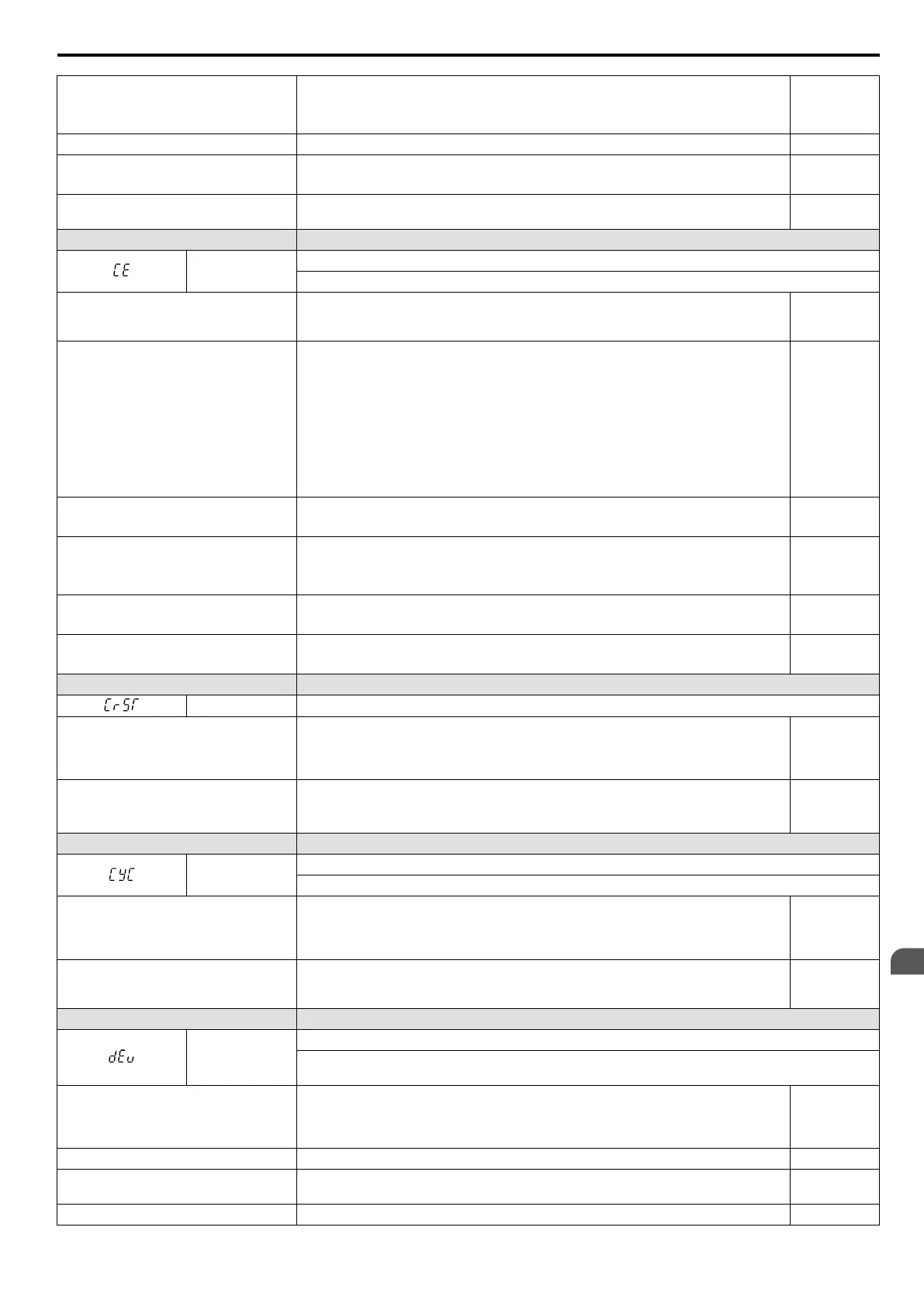
LED Operator Display Minor Fault Name
CE
MEMOBUS/Modbus Communication Error
Control data was not received correctly for two seconds.
Cause Possible Solutions
Minor Fault
(H2-oo =
10)
A data error occurred due to noise.
• Check options available to minimize the effects of noise.
• Counteract noise in the control circuit wiring, main circuit lines and ground wiring.
• Reduce noise on the controller side.
• Use surge absorbers on magnetic contactors or other equipment causing the
disturbance.
• Use cables recommended by Yaskawa or another type of shielded line. The shield
should be grounded on the controller side or on the drive input power side.
• Separate all wiring for communications devices from drive input power lines. Install
an EMC noise filter to the input side of the drive input power.
YES
Communication protocol is incompatible.
• Check the H5 parameter settings as well as the protocol setting in the controller.
• Ensure settings are compatible.
YES
The CE detection time (H5-09) is set
shorter than the time required for a
communication cycle to take place.
•
Check the PLC.
• Change the software settings in the PLC.
• Set a longer CE detection time (H5-09).
YES
Incompatible PLC software settings or
there is a hardware problem.
• Check the PLC.
• Remove the cause of the error on the controller side.
YES
Communications cable is disconnected or
damaged.
• Check the connector for a signal through the cable.
• Replace the communications cable.
YES
LED Operator Display Minor Fault Name
CrST Can Not Reset
Cause Possible Solutions
Minor Fault
Output
(H2-oo =
10)
Fault reset was being executed when a run
command was entered.
• Ensure that a run command cannot be entered from the external terminals or option
card during fault reset.
• Turn off the run command.
YES
LED Operator Display Minor Fault Name
CyC
MECHATROLINK Comm. Cycle Setting Error
Comm. Cycle Setting Error was detected.
Cause Possible Solutions
Minor Fault
Output
(H2-oo =
10)
The controller is using a comm. cycle
beyond
the allowable setting range for the
MECHATROLINK option unit.
Set the comm. cycle for the upper controller within the allowable setting range for the
MECHATROLINK option unit.
YES
LED Operator Display Minor Fault Name
dEv
Speed Deviation (for Simple V/f with PG)
According to the pulse input (RP), the speed deviation is greater than the setting in F1-10 for a time
longer than the setting in F1-11.
Cause Possible Solutions
Minor Fault
Output
(H2-oo =
10)
Load is too heavy Reduce the load. YES
Acceleration and deceleration times are
set too short.
Increase the acceleration and deceleration times (C1-01 through C1-08). YES
The load is locked up. Check the machine. YES
6.5 Alarm Detection
YASKAWA ELECTRIC SIEP C710606 16C YASKAWA AC Drive – V1000 Technical Manual
267
6
Troubleshooting

 Loading...


