Cause Possible Solutions
The drive has been set to accept
the frequency reference from the
incorrect source.
Check parameter b1-01 (Frequency Reference Selection 1).
Set b1-01 to the correct source of the frequency reference.
0: LED operator
1: Control circuit terminal (default setting)
2: MEMOBUS/Modbus communications
3: Option card
4: Pulse train input (RP)
The terminal set to accept the
main speed reference is set to the
incorrect voltage and/or current.
If the frequency reference is set at terminal A1, check parameter H3-01 for the correct signal level selection. If
terminal A2 is used, check DIP switch S1. Then select the correct input level for terminal A2 in parameter H3-08.
Refer to DIP Switch S1 Analog Input Signal Selection on page 69.
Selection for the sink/source
mode is incorrect.
Check DIP switch S3. Refer to Sinking/Sourcing Mode Switch on page 67.
Frequency reference is too low.
• Check the frequency reference monitor (U1-01).
• Increase the frequency by changing the maximum output frequency (E1-09).
Multi-function analog input is
set up to accept gain for the
frequency reference, but no
voltage (current) has been
provided.
• Check the multi-function analog input settings.
• Check if analog input A1 or A2 is set for frequency reference gain (H3-02/10 = 1). If so, check if the correct
signal is applied to the terminal. The gain and the frequency reference will be 0 if no signal is applied to the
gain input.
• Check if H3-02 and H3-10 have been set to the proper values.
• Check if the analog input value has been set properly.
The
STOP
button was pressed
when the drive was started from
a REMOTE source.
•
When the
STOP
button is pressed, the drive will decelerate to stop.
• Switch off the run command and then re-enter a run command.
•
The
STOP
button is disabled when o2-02 is set to 0.
Motor is not producing enough
torque in the V/f motor control
method.
• Ensure the selected V/f pattern corresponds with the characteristics of the motor being used.
• Set the correct V/f pattern to E1-03.
• When E1-03 = F, increase both the minimum and mid output frequency voltages (E1-08, E1-10).
Increase the frequency reference so that it is higher than the minimum frequency reference (E1-09).
Perform Line-to-Line Resistance Auto-Tuning when using particularly long motor cables.
Increase the torque compensation gain (C4-01).
Motor is not producing enough
torque in Open Loop Vector
Control.
• Execute Rotational Auto-Tuning.
•
If the motor cables are replaced with longer cables after Rotational Auto-Tuning was performed, Auto-Tuning
may need to be repeated due to voltage drop across the line.
• Check if the torque limit parameters have been set too low (L7-01 through L7-04).
• Reset the torque limit back to its default setting (200%).
Increase both the minimum and mid output frequency voltages (E1-08 and E1-10).
The drive is set for both 2-Wire
and 3-Wire sequence at the same
time.
• The drive is set for a 3-Wire sequence when one of parameters H1-03 through H1-07 is set to 0.
• If the drive is supposed to be set up for a 2-Wire sequence, then ensure parameters H1-03 through H1-07 are
not set to 0.
•
If the drive is supposed to be set up for a 3-Wire sequence, then H1-oo
must be set to 0.
n
Motor Rotates in the Opposite Direction from the Run Command
Cause Possible Solutions
Phase wiring between the drive and motor is incorrect.
• Check the motor wiring.
• Switch two motor cables (U, V, and W) to reverse motor direction.
• Connect drive output terminals U/T1, V/T2 and W/T3 in the right order to the
corresponding motor terminals U, V, and W.
• Change the setting of parameter b1-14.
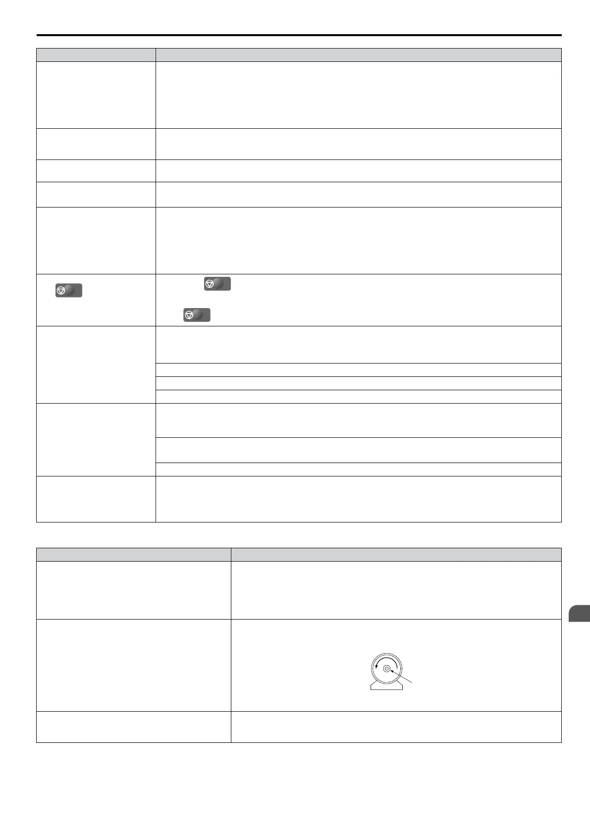
The forward direction for the motor is setup
incorrectly.
Typically, forward is designated as being counterclockwise when looking from the motor
shaft (refer to the figure below).
1
2
1. Forward Rotating Motor (looking down the motor shaft)
2. Motor Shaft
The motor is running at almost 0 Hz and the Speed
Search estimated the speed to be in the opposite
direction.
• Disable bi-directional search (b3-14 = “0”) so that Speed Search is performed only in the
specified direction.
Note: Check the motor specifications for the forward and reverse directions. The motor specifications will vary depending on the manufacturer
of the motor.
6.9 Troubleshooting without Fault Display
YASKAWA ELECTRIC SIEP C710606 16C YASKAWA AC Drive – V1000 Technical Manual
281
6
Troubleshooting

 Loading...


