n
Single-Phase AC 200 V BA0006B to BA0018B
Three-Phase AC 200 V 2A0008B to 2A0020B
Three-Phase AC 400 V 4A0001B to 4A0011B
A
B
C
D
E
F
G
H
I
J
M
K
L
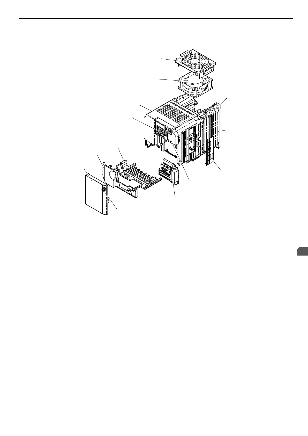
A –
Fan cover
<1>
B – Mounting hole
C – Heatsink
D – Optional 24 VDC power supply
connector cover
E – Comm port
F – Terminal board Refer to Control
Circuit Terminal Block Functions
on page 63
G – Front cover screw
H – Front cover
I – Terminal cover
J – Bottom cover
K – LED operator Refer to Using the
Digital LED Operator on page
78
L – Case
M –
Cooling fan
<1>
Figure 1.3 Exploded View of IP20/Open-Chassis Type Components (Model 2A0012B)
<1> Models BA0006B and 4A0001B to 4A0004B do not have a cooling fan or a cooling fan cover. Model BA0018B has two
cooling fans.
1.4 Component Names
YASKAWA ELECTRIC SIEP C710606 16C YASKAWA AC Drive – V1000 Technical Manual
31
1
Receiving

 Loading...


