No. Name Description Range Def.
Control
Mode
Addr. Hex Pg.
V/f
O
LV
PM
E3-04
Motor 2 Max
Output Frequency
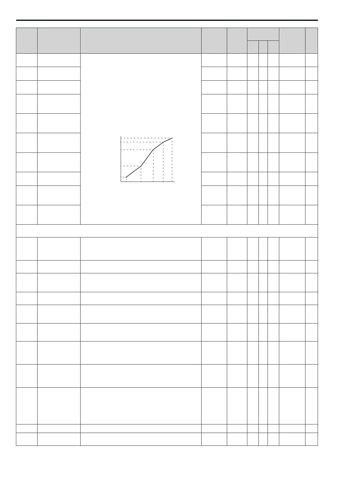
To set linear V/f characteristics, set the same values for
E3-07
and E3-09. In this case, the setting
for E3-08 will be
disregarded.
Ensure that the five frequencies are set according to these
rules to prevent triggering an oPE10 fault:
E3-09 ≤ E3-07 < E3-06 ≤ Ε3−11 ≤ E3-04
Note: Setting E3-11 to 0 disables both E3-11 and E3-12,
and the above conditions do not apply.
E3-09 E3-07 E3-06 E3-11 E3-04
E3-05
E3-12
E3-13
E3-08
E3-10
VACrms Out (V)
Frequency (Hz)
40.0 to
400.0
60 Hz
<19>
A A − 31A 167
E3-05
<1>
Motor 2 Max
Voltage
0.0 to
255.0
200.0 V A A − 31B 167
E3-06
Motor 2 Base
Frequency
0.0 to
E3-04
60 Hz
<19>
A A − 31C 167
E3-07
Motor 2 Mid Output
Freq.
0.0 to
E3-04
3.0 Hz
<12>
<19>
A A − 31D 167
E3-08
<1>
Motor 2 Mid Output
Freq. Voltage
0.0 to
255.0
16.0 V
<6>
<12>
A A − 31E 167
E3-09
Motor 2 Min.
Output Freq.
0.0 to
E3-04
1.5 Hz
<12>
<19>
A A − 31F 167
E3-10
<1>
Motor 2 Min.
Output Freq.
Voltage
0.0 to
255.0
12.0 V
<6>
<12>
A A − 320 167
E3-11
<7>
Motor 2 Mid Output
Frequency 2
0.0 to
E3-04
0.0 Hz A A − 345 167
E3-12
<1>
<13>
Motor 2 Mid Output
Frequency Voltage
2
0.0 to
255.0
<1>
0.0 Vac A A − 346 167
E3-13
<1>
<9>
Motor 2 Base
Voltage
0.0 to
255.0
<1>
0.0 Vac A S − 347 167
E4: Motor 2 Parameters
Use E4 parameters to control a second motor operating on the same drive.
E4-01
Motor 2 Rated
Current
Sets the motor 2 nameplate full load current in amperes
(A). This value is automatically set during Auto-Tuning.
10 to 200%
of drive
rated
current
<10>
A A − 321 168
E4-02
Motor 2 Rated
Slip
Sets the motor 2 rated slip in Hz. Automatically set during
Auto-Tuning.
0.00 to
20.00
<10>
A A − 322 168
E4-03
Motor 2 Rated No-
Load Current
Sets the magnetizing current of motor 2 in Ampere.
Automatically set during Rotational Auto-Tuning.
0 to less
than E4-01
<9>
<10>
A A − 323 169
E4-04
Motor 2 Motor
Poles
Sets the number of poles of motor 2. This value is
automatically set during Auto-Tuning.
2 to 48 4 poles A A − 324 169
E4-05
Motor 2 Line-to-
Line Resistance
Sets the phase-to-phase resistance of motor 2 in ohms.
Automatically during Auto-Tuning.
0.000 to
65.000
<11>
<10>
A A − 325 169
E4-06
Motor 2 Leakage
Inductance
Sets the voltage drop due to motor leakage inductance as a
percentage of rated voltage of motor 2. Automatically set
during Auto-Tuning.
0.0 to 40.0
<10>
A A − 326 169
E4-07
Motor 2 Motor
Iron-Core
Saturation
Coefficient 1
Set to the motor iron saturation coefficient at 50% of
magnetic flux. Automatically set during Rotational
Auto-Tuning.
0.00 to
0.50
0.50 − A − 343 169
E4-08
Motor 2 Motor
Iron-Core
Saturation
Coefficient 2
Set to the motor iron saturation coefficient at 75% of
magnetic flux. This value is automatically set during
Rotational Auto-Tuning.
Setting for
E4-07 to
0.75
0.75 − A − 344 169
E4-09
Motor 2
Mechanical Loss
Sets the motor mechanical loss as a percentage of motor
rated power (kW) capacity.
Adjust in the following circumstances:
• When
there is a large amount of torque
loss due to motor
bearing friction.
• When there is a large amount of torque loss.
0.00 to
10.0
0.0 − A − 33F 169
E4-10 Motor 2 Iron Loss Sets the motor iron loss in watts. 0 to 65535
<10>
Α − − 340 170
E4-11
Motor 2 Rated
Capacity
Sets the motor rated capacity in kW. Automatically set
during Auto-Tuning.
0.00 to
650.00
<6>
A A − 327 170
B.2 Parameter Table
344
YASKAWA ELECTRIC SIEP C710606 16C YASKAWA AC Drive – V1000 Technical Manual

 Loading...


