+
-
1 MCCB
MC
2 MCCB
r1
s1
t1
<3>
R/L1
S/L2
T/L3
For single-phase
200 V power supply
use R/L1 and S/L2.
Three phase
power supply
for 200 V / 400 V
Terminals +1, +2, − , B1, and B2
are for connecting options.
Never connect power supply
lines to these terminals.
Digital inputs
(default setting)
Forward run/stop
Reverse run/stop
External fault
Fault reset
Multi-step
speed 2
Jog reference
S1
S2
S3
S4
S5
S6
S7
Multi-step
speed 1
main/aux switch
<4>
DC link choke
(option)
V1000
Thermal relay
(option)
Main circuit
Control circuit
R/L1
S/L2
T/L3
<1>
<2>
-
B1+1+2 B2
Jumper
Motor
Cooling fan
Braking resistor
(option)
U/T1
V/T2
W/T3
M
M
r1
s1
t1
FU
FV
FW
U
V
W
Ground
10
or less (400 V class)
100
or less (200 V class)
Digital output
250 Vac, 10 mA to 1 A
30 Vdc, 10 mA to 1 A
(default setting)
Option card
connector
Fault
MA
P1
MB
MC
P2
MP
PC
During Run
(photocoupler 1)
Frequency agree
(photocoupler 2)
Photocoupler
output common
Digital output
5 to 48 Vdc
2 to 50 mA
(default setting)
Pulse train output
0 to +10 Vdc
(2 mA)
Comm.
connector
AM
AC
AM
0 to 32 kHz
Analog monitor
output
Termination
resistor
Monitor
output
<6>
IG
R
+
R
-
S
+
S
-
MEMOBUS/
Modbus comm.
RS-485/422
120
, 1/2 W
Cable shield ground
DIP
switch
S2
main circuit terminal
shielded line
twisted-pair shielded line
control terminal
Safe Disable
Input
Safety switch
HC
H1
Jumper
<7>
Main speed
frequency
reference.
Multi-function
programmable
RP
+V
A1
A2
AC
2 k
Pulse train input
(max. 32 kHz)
0 to +10 V (20 k
)
Setting power supply
+10.5 max. 20 mA
0 to +10 V (20 k
)
(0)4 to 20 mA (250
)
DIP
switch S3
Shield ground
terminal
0 V
SC
Sink
Source
<5>
24 V
+
24 V 8 mA
Wiring sequence should shut off
power to the drive when a fault
<8>
output is triggered.
TRX
ON
OFF
THRX
SA
1
2
TRX
MC
MC
MB
TRX
Fault relay contact
Braking resistor unit
Thermal relay trip contact
MC
SA
SA
THRX
V I
DIP switch S1
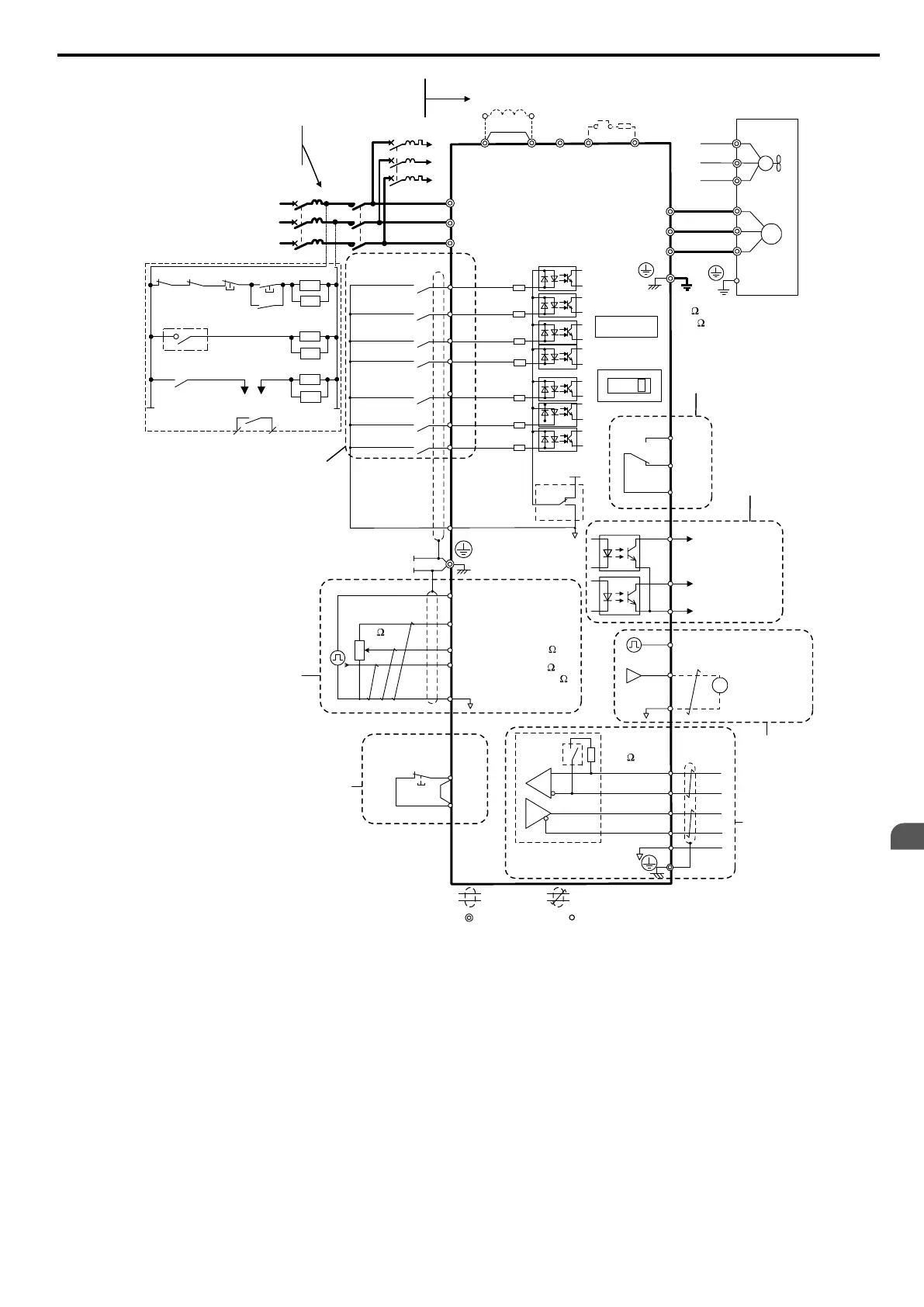
Figure 3.1 Drive Standard Connection Diagram
<1> Remove the jumper when installing an optional DC reactor.
<2> The MC on the input side of the main circuit should open when the thermal relay is triggered.
<3> Self-cooled motors do not require separate cooling fan motor wiring.
<4> Connected using sequence input signal (S1 to S7) from NPN transistor; Default: sink mode (0 V com).
<5> Use only a +24 V internal power supply in sinking mode; the source mode requires an external power supply. Refer
to I/O Connections on page 67 for details.
<6> Monitor outputs work with devices such as analog frequency meters, ammeters, voltmeters and wattmeters; they
are not intended for use as a feedback-type of signal.
<7> Disconnect the wire jumper between HC and H1 when utilizing the safety input. Refer to Wiring Procedure on
page 65 for details on removing the jumper. The wire length for the Safe Disable input should not exceed 30 m.
<8> Note that if the drive is set to trigger a fault output whenever the fault restart function is activated (L5-02 = 1), then
a sequence to interrupt power when a fault occurs will result in shutting off the power to the drive as the drive
attempts to restart itself. The default setting for L5-02 is 0 (fault output active during restart attempt).
3.2 Standard Connection Diagram
YASKAWA ELECTRIC SIEP C710606 16C YASKAWA AC Drive – V1000 Technical Manual
49
3
Electrical Installation

 Loading...


