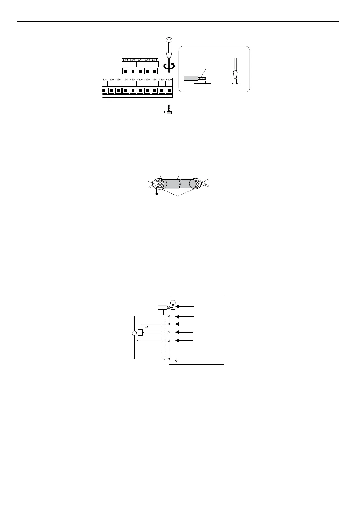
Preparing wire
terminal ends
E
A
B
D
C
A – Control terminal block
B
–
Avoid fraying wire strands when
stripping insulation from wire.
Strip length 5.5 mm.
C
–
Single wire or stranded wire
D
–
Loosen screw to insert wire.
E
–
Blade depth of 0.4 mm or less
Blade width of 2.5 mm or less
Figure 3.20 Terminal Board Wiring Guide
A
F
C
D
E
B
A – Drive side
B – Connect shield to ground terminal
of drive.
C – Insulation
D – Control device side
E – Shield sheath (Insulate with tape)
F – Shield
Figure 3.21 Preparing the Ends of Shielded Cables
When setting the frequency by analog reference from an external potentiometer, use shielded twisted-pair wires and ground
the shield of twisted-pair wires to the ground terminal of the drive.
NOTICE: The analog signal lines between the drive and the operator station or peripheral equipment should not exceed 50 meters
when using an analog signal from a remote source to supply the frequency reference. Failure to comply could result in poor system
performance.
RP
+V
A1
A2
AC
A
B
C
D
E
F
G
2 k
A – Drive
B – Ground terminal (shield
connection)
C – (RP) Pulse train (maximum 32
kHz)
D – (+V) Frequency setting power
source +10.5
Vdc maximum 20 mA
E – (A1) Main speed frequency
reference 0 to +10 Vdc (20 kΩ)
F – (A2) Multi-function analog input
0 to +10 Vdc (20 kΩ) or
4 to 20 mA (250 Ω)/
0 to 20 mA (250 Ω)
G – Frequency setting potentiometer
Figure 3.22 Wiring the Frequency Reference to the Control Circuit Terminals (External Reference)
3.7 Control Circuit Wiring
66
YASKAWA ELECTRIC SIEP C710606 16C YASKAWA AC Drive – V1000 Technical Manual

 Loading...


