<4.Conguration>
23
IM 01E21A02-03EN
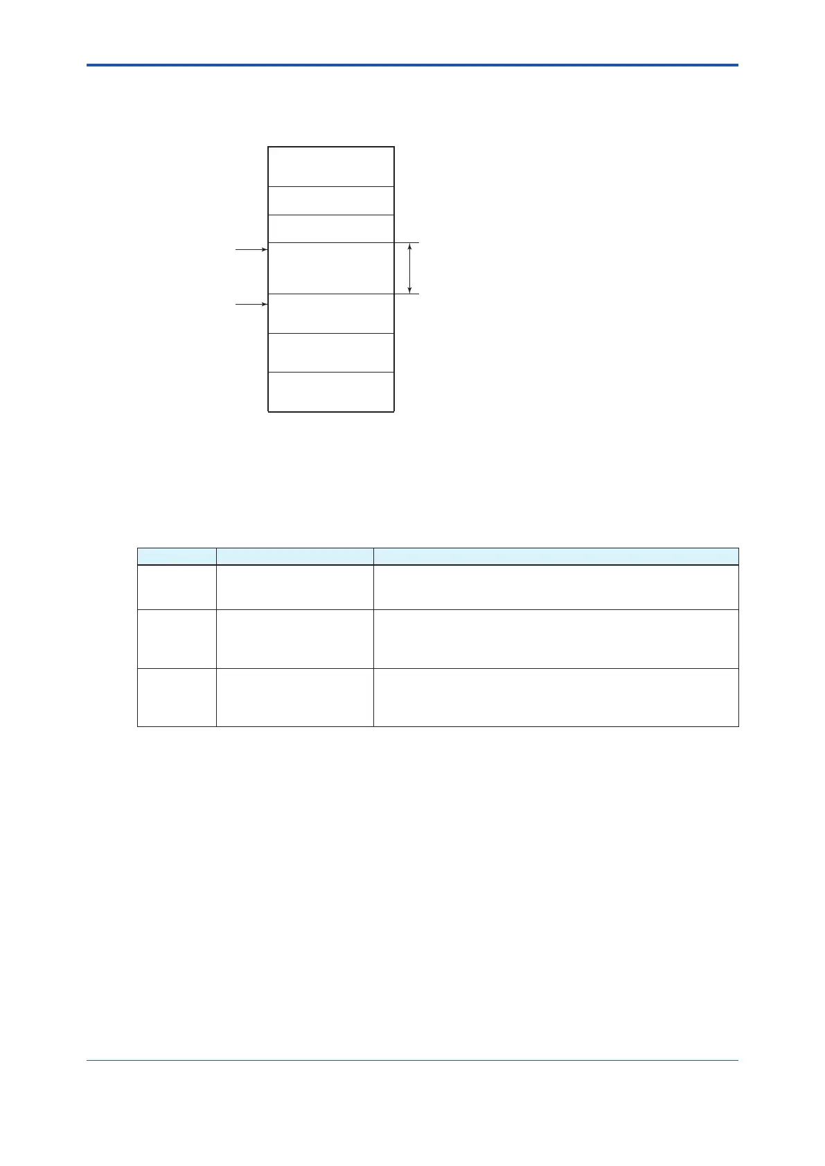
Thedeviceswithintheaddressrangewrittenas“Unused”inFigure4.1cannotbeusedon
Fieldbus. For other address ranges, the range is periodically checked to identify when a new
device is mounted. Care must be taken to keep the unused device range as narrow as possible
so as to lessen the load on Fieldbus.
0xF7
0xF8
0xFB
0xFC
0xFF
V(FUN)
V(FUN)+V(NUN)
LM device
Unused V(NUN)
BASIC device
Default address
Portable device address
F0401.EPS
Not used
0x00
0x0F
0x10
0x13
0x14
Bridge device
Figure 4.1 Available Range of Node Addresses
To ensure stable operation of Fieldbus, determine the operation parameters and set them to
the LM devices. When the parameters in Table 4.2 are to be set, the worst-case value of all the
devicestobeconnectedtothesameFieldbusmustbeused.Refertothespecicationsofeach
devicefordetails.Table4.2listsspecicationvaluesofthisproduct.
Table 4.2 Operation Parameter Values of This Product to be Set to LM Devices
Symbol Parameter Name Description and Setting
V(ST) Slot-Time
Indicates the time necessary for the immediate reply of the device.
Unitoftimeisinoctets(256µs).Setthemaximumspecicationfor
all devices. For this product, set a value of 4 or greater.
V(MID) Minimum-Inter-PDU-Delay
Indicates the minimum value of communication data intervals to
startreply.Unitoftimeisinoctets(256µs).Setthemaximum
specicationforalldevices.Forthisproduct,setavalueof4or
greater.
V(MRD) Maximum-Response-Delay
Indicates the worst-case time elapsed until a reply is received.
SincetheunitisSlot-time,setthevaluesothatV(MRD)xV(ST)
isthemaximumvalueofthespecicationsforalldevices.Forthis
product,setV(MRD)xV(ST)toavalueof12orgreater.

 Loading...


