<Appendix 2. Integrator (It) Block>
241
IM 01E21A02-03EN
Appendix 2. Integrator (IT) Block
The IT block adds two main inputs and integrates them for output. The block compares the
outputs with TOTAL_SP and PRE_TRIP and generates signals when the limits are reached
(OUT_TRIPoutput,OUT_PTRIPoutput).
Theoutputisasrepresentedbythefollowingequation(forcountingUPandRATEconversion).
OUT=Integrationstartvalue+Total
Total=Total+CurrentIntegral
CurrentIntegral=(x+y)xΔt
x : IN_1 value whose unit has been converted
y : IN_2 value whose unit has been converted
Δt :blockexecutionperiod
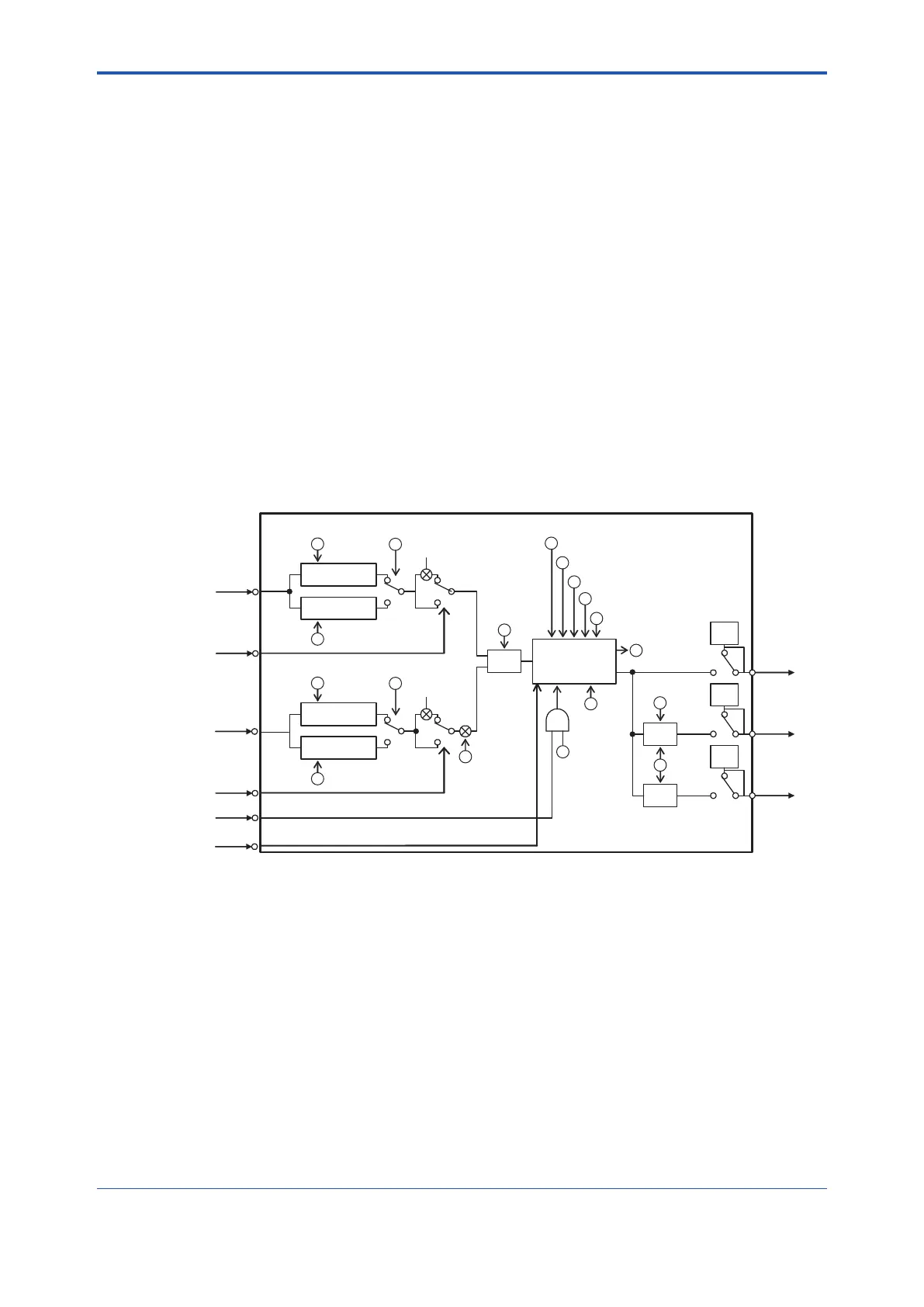
A2.1 Schematic Function Diagram of Integrator
Block
The functional block diagram of the IT block is shown below.
OUT
IN_1
RESET_IN
REV_FLOW1
–1
TIME_UNIT2
IN_2
REV_FLOW2
PULSE_VAL2
–1
UNIT_CONV
OP_CMD_INT
(RESET)
INTEG_OPTS
(CARRY)
Reverse
Forward
Forward
OUT_PTRIP
OUT_TRIP
INTEG_OPTS
(FLOW TYPE)
Add
Compare
Compare
TOTAL / RTOTAL
Integrate
INTEG_TYPE
INTEG_OPTS (QUALITY)
GOOD_LIM
UNCERT_LIM
CLOCK_PER
N_RESET
MAN
MAN
MAN
Convert Rate
Convert Accum
Convert Rate
Convert Accum
TOTAL_SP
PRE_TRIP
INTEG_OPTS
(INPUT TYPE)
PULSE_VAL1
TIME_UNIT1
INTEG_OPTS
(INPUT TYPE)
RESET_CONFIRM
Reverse
FA0201.EPS
IN_1 ................................ Blockinput1(value&status).
IN_2 ................................ Blockinput2(value&status).
REV_FLOW1 .................. Indicates whether the sign of IN_1 is reversed.
Discrete signal.
REV_FLOW2 .................. Indicates whether the sign of IN_2 is reversed.
Discrete signal.
RESET_IN ...................... RESET signal of the integrated values. Discrete signal.
RESET_CONFIRM......... RESETconrmationinput.Discretesignal.
OUT ................................ Output(value&status).
OUT_PTRIP.................... Set if the target value PRE_TRIP is exceeded. Discrete signal.
OUT_TRIP ...................... SetwhenthetargetvalueexceedsTOTAL_SP(or0).Discretesignal.

 Loading...


