<Appendix 5. PID Block>
293
IM 01E21A02-03EN
A5.19 Example of Block Connections
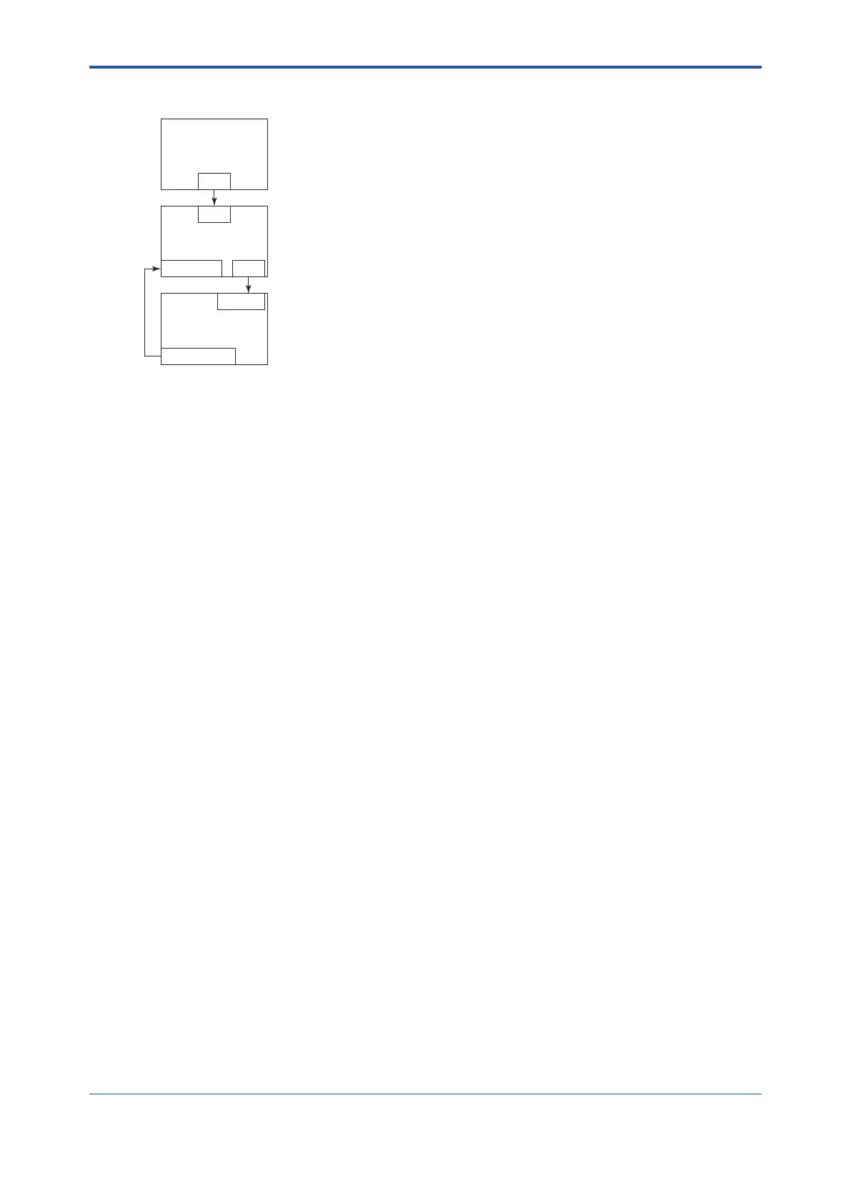
PID
BKCAL_IN OUT
IN
AO
BKCAL_OUT
CAS_IN
AI
OUT
FA0106.ai
TouseasimplePIDcontrolloopbycombiningavalvepositioner(devicewithAO)withasensor
device, the setting procedures for each block are explained based on the basic connection
example of PID.
(1) ConnecttheAIblockandPIDblockofthesensordevice,andtheAOblockofthevalve
positioner as shown above.
(2) SetGAIN,RESET,andRATEparametersbysettingtheMODE_BLKtargetofthePIDblock
to O/S.
(3) CheckthatthevalueofMODE_BLKactualoftheAIblockisAuto.
(4) SettheMODE_BLKtargetoftheAOblocktoCas|Auto.
(5) CheckthatthevalueofBKCAL_INstatusofthePIDblockisnotBAD.
(6) CheckthatthevalueofINstatusofthePIDblockisnotBAD.
(7) CheckthatAutoissettothepermittedmodeinMODE_BLKofthePIDblock.
(8) SettheMODE_BLKtargetofthePIDblocktoAuto.
WhennishinguptoNo.8withthissetting,thePIDblockandAOblockexchangetherespective
information and initialize the cascade connection.
Byfollowingtheabovesteps,theactualofMODE_BLKofthePIDblockchangestoAutoandthe
automatic PID control starts.

 Loading...


