<5. Functions>
71
IM 01E21A02-03EN
5.3 Limit Switch Function
5.3.1 Limit Switch
The limit switch function is to transmit 0 and 1 as a parameter by judging whether the selected
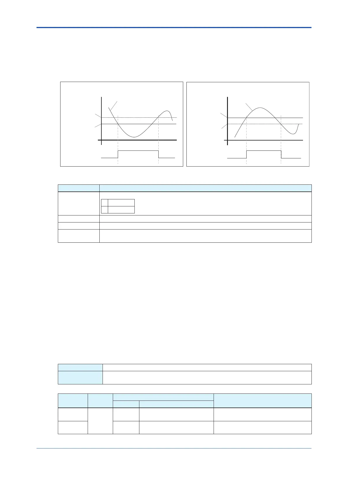
processvalueisaboveorbelowthethresholdvalue.Thefunctionoperatesasthegurebelow.
State 1
State 0
Active direction: Low limit
Set point + Hysteresis
Set point
Output
Process value
Time
Active direction: High limit
Set point
Set point - Hysteresis
Output
Process value
Time
State 1
State 0
Figure 5.3.1 Limit Switch Operational Schematic Figure
Function item Description of Parameter
Operation
direction
Speciestheoperationdirectionofthelimitswitch.
0 Low limit
1 High limit
Threshold Speciesthethresholdforjudgment.
Hysteresis Speciesthehysteresis(onlyapositivevaluecanbespecied).
Contact point
output
0(State0)or1(State1)isentered.
Figure 5.3.1 shows examples of the operation for a case where the operation direction is Low
limit on the left side and a case where the operation direction is High limit on the right side.
WhentheoperationdirectionisLowlimit,acontactpointoutputbecomes1(State1)ifthe
process value goes below the threshold. When the process value goes over the value obtained
byaddingthehysteresistothethreshold(threshold+hysteresis)afterthat,thecontactpoint
output becomes 0.
When the operation direction is High limit, the operation is opposite to the operation for Low
limit.Whenprocessvaluegoesoverthethreshold,thecontactpointoutputbecomes1(State
1).Whentheprocessvaluegoesbelowthevalueobtainedbydeductingthethresholdfromthe
hysteresis(threshold-hysteresis),thecontactpointoutputbecomes0.
On this product, two units of the above parameter and process value unit are prepared for each
process value. Meanwhile, the value of contact point output is updated only when selected by the
channel of the DI function block.
Flow velocity limit switch
Display --
F
OUNDATION
Fieldbus
DeviceConguration►STB►DeviceConguration►Conguration►LimitStsVelocity
►(seebelow)
Block
Name
Relative
Index
Parameter
Description
Display F
OUNDATION Fieldbus
STB
108
--
LimitStsVelocity1Value►
Lmt Sts Velo1.Status
Displays the status of the contact point
outputofowvelocitylimitswitch1.
STB --
LimitStsVelocity1Value►
Lmt Sts Velo1.Value
Displaysthecontactpointoutputofow
velocity limit switch 1.

 Loading...


