<Appendix 2. Integrator (It) Block>
242
IM 01E21A02-03EN
TheITblockisclassiedintothefollowingvesectionsforeachfunction:
• Input process section ........ Determines the input value status, converts RATE and ACCUM,
anddeterminestheinputowdirection.
• Adder ................................ Adds the two inputs.
• Integrator .......................... Integrates the result of the adder into the integrated value.
• Output process section ..... Determines the status and value of each output parameter.
• Reset process section ...... Resets the integrated value.
A2.2 Input Process Section
Whenexecuted,theITblockrstperformsinputprocessing.Theprocessingisexecutedinthe
followingorder:“Determininginputstatus”=>“ConvertingRATEorACCUM”=>“Determiningthe
inputowdirection”.SwitchingbetweenConvertRATEandConvertACCUMismadeusingbit
0(forIN_1)orbit1(forIN_2)ofINTEG_OPTS.INTEG_OPTSisoneofthesystemparameters,
and should be set by the user.
IN_1 and IN_2 are not be retained if the power is turned OFF.
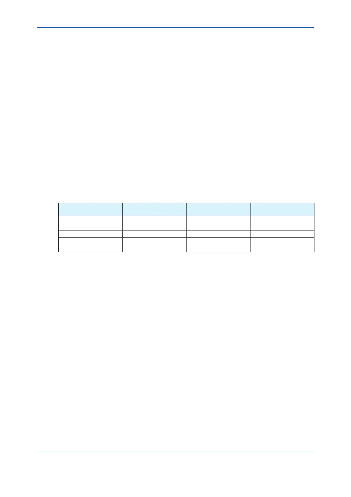
A2.2.1 Determining Input Value Statuses
Thefollowingshowsthecorrelationbetweenthestatusesofinputparameters(IN_1,IN_2)and
the statuses of input values used in the IT block.
Status of input
parameter (IN_1, IN_2)
Bit4 of INTEG_OPTS
(Use uncertain)
Bit5 of INTEG_OPTS*
(Use Bad)
Status of input value
handled in the IT block
Good Irrelevant Irrelevant Good
Bad Irrelevant H(=1) Good
Bad Irrelevant L(=0) Bad
Uncertain H(=1) Irrelevant Good
Uncertain L(=0) Irrelevant Bad
Foraddition(seeA2.3),ifthestatusofaninputvalueis“Bad”,the“Good”valuejustbeforethe
statuschangedto“Bad”isused.
*EveniftheUseBadoptionisappliedandtheinternalstatusis“Good”,thevalueof“Good”just
beforethestatuschangedto“Bad”isused.

 Loading...


