<4.Conguration>
22
IM 01E21A02-03EN
z Cable:
Usedforconnectingdevices.Referto“FieldbusTechnicalInformation”(TI38K03A01-01E)
fordetailsofinstrumentationcabling.Foreldbranchcabling,useterminalboardsora
connection box as required.
First, check the capacity of the power supply. The power supply capacity must be greater than
the sum of the maximum current consumed by all devices to be connected to Fieldbus. The
maximumcurrentconsumed(powersupplyvoltage9Vto32V)forthisproductis15mA.
The cable used for the spur must be of the minimum possible length.
4.2 NetworkDenition
BeforeconnectingdeviceswithFieldbus,denetheFieldbusnetwork.AllocatethePDtagand
nodeaddressestoalldevices(excludingsuchpassivedevicesasterminators).
The PD tag is the same as the conventional one used for the device. Up to 32 alphanumeric
charactersmaybeusedfordenition.Useahyphenasadelimiterasrequired.
The node address is used to specify devices for communication purposes. Because this
data is too long for the PD Tag, the host uses the node address in place of the PD Tag for
communication.Therangeof20to247(orfrom14toF7inhexadecimalnotation)canbeset.
Thedevice(LMdevice)withbuscontrolfunction(LinkMasterfunction)isallocatedfroma
smalleraddressnumber(20)side,andotherdevices(BASICdevice)withoutbuscontrolfunction
allocatedfromalargeraddressnumber(247)siderespectively.Settherangeofaddressestobe
used to the LM device. Set the following parameters.
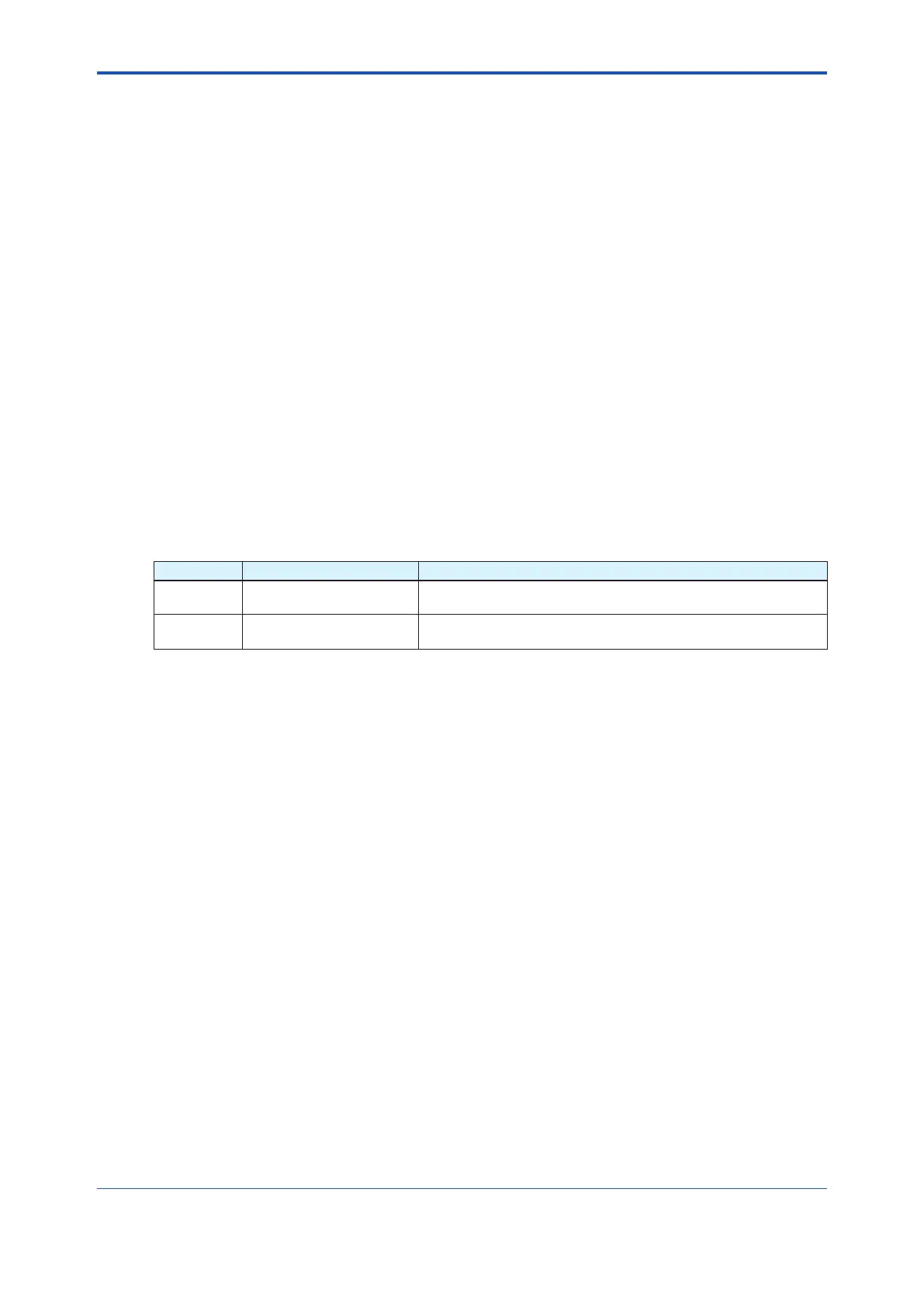
Table 4.1 Parameters for Setting Address Range
Symbol Parameter Name Description
V(FUN) First-Unpolled-Node
Sets the address next to the address range used for the host or
other LM device.
V(NUN)
Number-of-consecutive-
Unpolled-Node
Unused address range.

 Loading...


