Chapter 7 Camera Cable Pin and Signal Information
156 Adept MV Controller User’s Guide, Rev. B
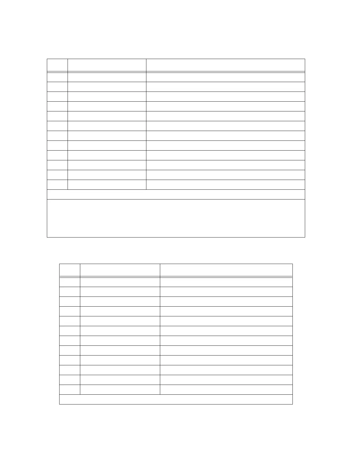
Table 7-7. Breakout Cable Camera Connector Pin Assignments (RS-170)
Pin Function Notes
1 Power return
2 +12V power to camera
3 Shield (video)
4 Video from camera
5 Shield (Hd)
6 Hd (horizontal drive) to camera
7 Vd (vertical drive) to camera
8 Shield (Clock) to camera (camera 1 & 2 only)
9 Clock to camera (camera 1 & 2 only)
10 not connected
11 not connected
12 Shield (Vd)
12-Pin Hirose Female Jack, HR10A-10J-12S
This connector will normally be connected to the camera using the optional
10-meter camera extension cable.
For special applications, this connector will mate with a Hirose Male Plug
HR10A-10P-12P (user-supplied) or similar plug. See
Figure 7-9
for pin locations.
Table 7-8. Breakout Cable Camera Connector Pin Assignments (for Pulnix TM-1001)
Pin Function Notes
1Power return
2 +12V power to camera
3 Shield (video)
4 Video from camera
5 Shield (Hd)
6 Hd (horizontal drive) from camera to LEN (line enable)
7 Vd (vertical drive) from camera to FEN (frame enable)
8 Shield (Clock)
9 Clock from camera to VSCLOCK (pixel clock)
10 not connected
11 not connected
12 Shield (Vd)
12-Pin Hirose Female Jack, HR10A-10J-12S
Artisan Technology Group - Quality Instrumentation ... Guaranteed | (888) 88-SOURCE | www.artisantg.com