Chapter 7 Camera Cable Pin and Signal Information
Adept MV Controller User’s Guide, Rev. B 157
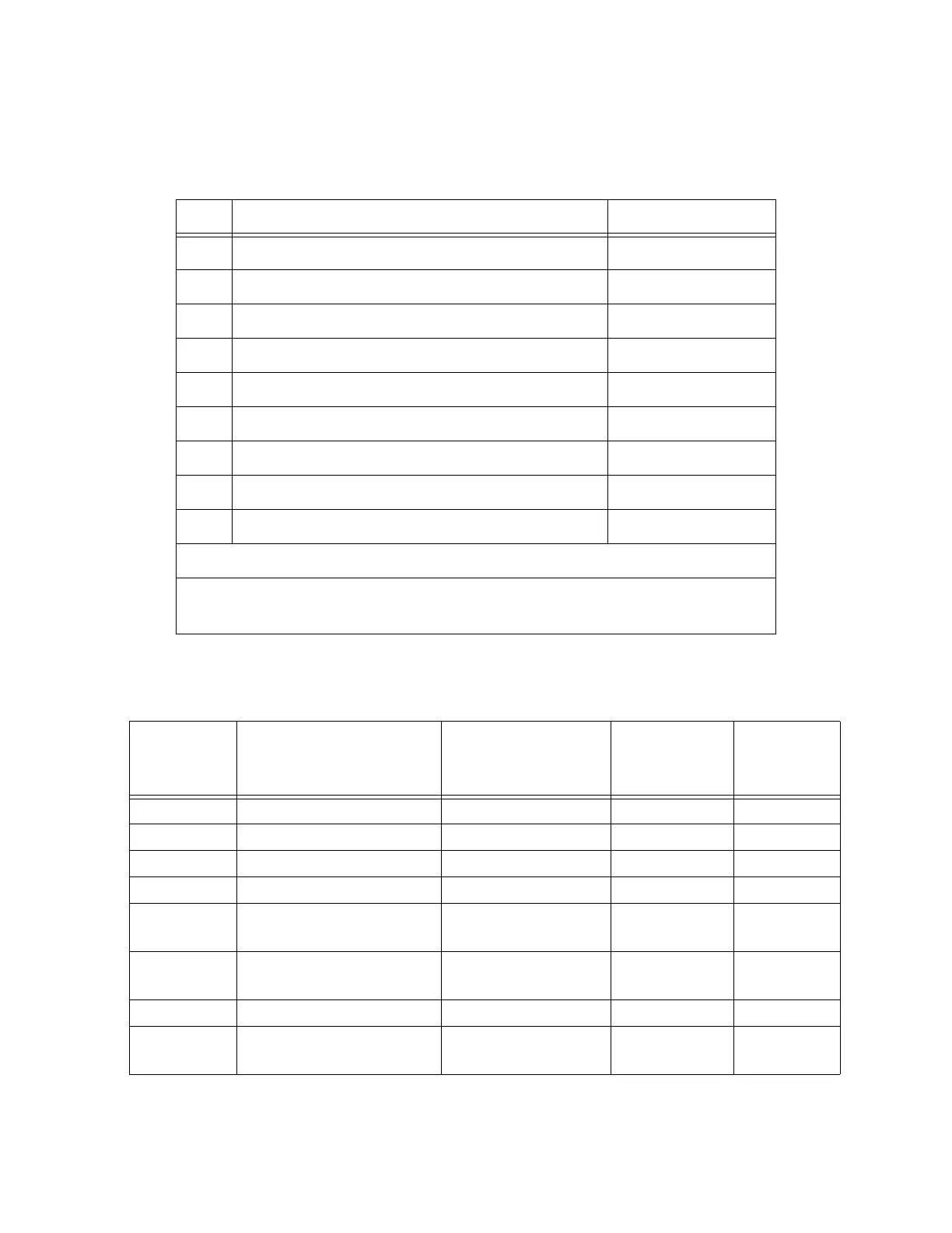
Table 7-9. Breakout Cable Strobe and Power Connector Pin Assignments (for Pulnix
TM-1001)
Pin Function Notes
1
User +12 VDC to cameras
2
User power return (Gnd)
3
Strobe 1
4
Strobe return (Gnd)
5
Strobe 2
6
Frame Reset 1
7
Frame Reset return (Gnd)
8
Frame Reset 2
9
Shield (chassis ground)
9-Pin D-Sub Female Receptacle
Note: this connector will mate with the 9-pin D-Sub male plug on the
BNC adapter cable.
Table 7-10. Adept 10-Meter Camera Cable Pin Assignments
Pin # at
controller
end (male) Function Notes
Wire Color
(typical)
Pin # at
camera end,
(female)
1
Power return gray
1
2
+12V power to camera yellow
2
3
Shield (video) red-shield
3
4
Video from camera red-signal
4
5
Shield (Hd) orange-
shield
5
6
Hd (horizontal drive) to camera orange-
signal
6
7
Vd (vertical drive) to camera black-signal
7
8
Shield (Clock) to camera (cam. 1
& 2 only)
white-shield
8
Artisan Technology Group - Quality Instrumentation ... Guaranteed | (888) 88-SOURCE | www.artisantg.com