Chapter 7 Camera Cable Pin and Signal Information
158 Adept MV Controller User’s Guide, Rev. B
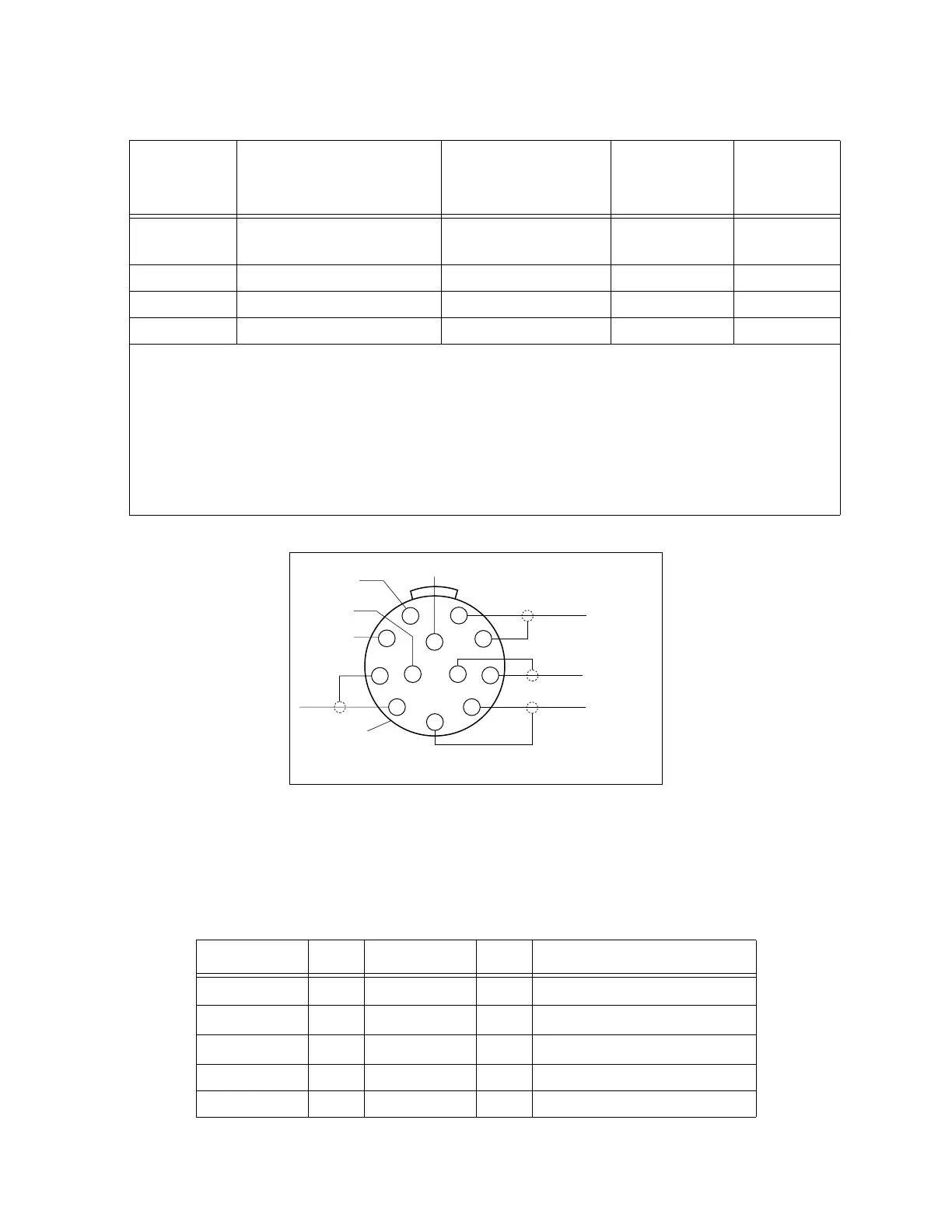
Figure 7-9. Pin Locations for Camera Cable Connector (12-Pin Hirose Male)
9
Pixel clock to camera (cam. 1
& 2 only)
white-signal
9
10
not used reserved brown
10
11
not used reserved blue
11
12
Shield (Vd) black-shield
12
• Connector at controller end: 12-Pin Hirose Male, HR10A-10P-12P, with ground
terminal lug (shield). See Figure 7-9 for pin locations.
• Connector at camera end: 12-Pin Hirose Female, HR10A-10P-12S.
• Cable specifications: 12 conductors, including 4 coax pairs, 4 discrete
conductors, and overall shield. At each end the shield is clamped to connector
body.
Table 7-11. Four-Camera Breakout Cable Pin Assignments
From: Pin To: Pin Function
Str/Pwr 2
CAM1
1 Power return
Str/Pwr 1
CAM1
2 +12V power
EVI
12
CAM1
3 Shield (video)
EVI
42
CAM1
4 Video
EVI
38
CAM1
5 Shield (Hd)
Table 7-10. Adept 10-Meter Camera Cable Pin Assignments (Continued)
Pin # at
controller
end (male) Function Notes
Wire Color
(typical)
Pin # at
camera end,
(female)
9
10
12
11
8
7
6
5
4
3
2
1
Black
Brown
Gray
Blue
Yellow
White
Orange
Red
Overall
Braided Shield
(Wire colors
may vary.)
Brown
Black
White
Orange
(Wire colors
may vary
Overall
Braided Shield
Red
Yellow
Blue
Gray
Artisan Technology Group - Quality Instrumentation ... Guaranteed | (888) 88-SOURCE | www.artisantg.com