6 Interaction devices
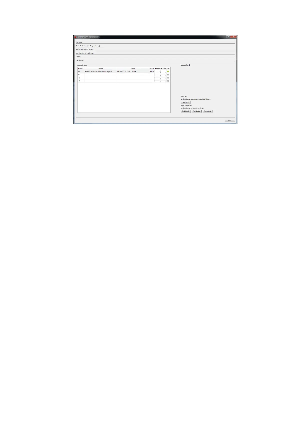
Figure 6.25: Fingertracking Administration - Tactile Device Test
pressing the corresponding buttons Test thumb, Test index or Test middle. The corre-
sponding status LED will light up to indicate radio communication (see figure figure 6.16
on page 88 and table 6.7 on page 88).
6.4.6.8 Fingertracking Output settings
The last step is to define where the Fingertracking data has to be sent to. In DTrack2 fron-
tend software, select Settings → Output. You can either select this computer (= remote
PC) or enter an IP address of another computer you want to send data to. By ticking the
checkboxes ’gl’ and ’glcal’ you can define the Fingertracking data to be transmitted.
Please refer to chapter 8.5.7 on page 160 for more details.
Press Start to start the measurement. In order to see the tracking data you have to enable
the Fingertracking display by clicking Display → Fingertracking. Please refer to chapter
8.3.3 on page 135 for details.
6.4.7 Display tool Fingertracking Viewer
The Fingertracking Viewer is a tool for visualisation of the hand and finger positions. It is
available free of charge for demonstration and testing purposes to be installed on the PC
that receives DTrack2 data.
After starting the viewer, proceed the following way:
• specify the ART Controller to connect to by defining the host name or IP address
• specify the UDP data port the viewer has to listen to
• press the Go Online button
100