8 DTrack2 frontend software
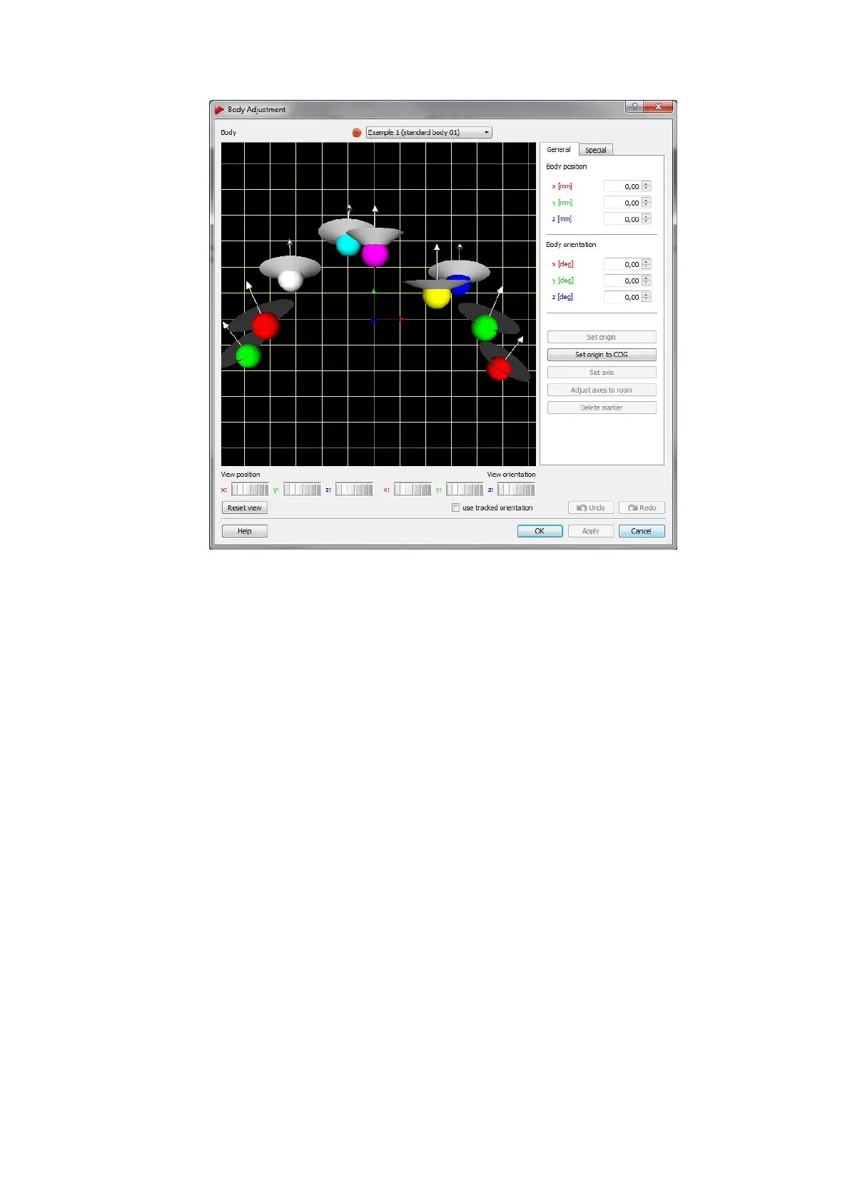
Figure 8.36: Body Adjustment
8.6.6.1 Graphic View
By default a cartesian coordinate system is displayed on the left side of the window de-
picting the selected rigid body’s geometry (’Graphic view’). On the right hand side the
body’s coordinate system can be manipulated. The body coordinate system is shown as
a triplet of arrows with a defined color-coding (x-axis: red, y-axis: green, z-axis: blue),
while the xy-plane is shown as a yellow grid. All markers, however, are visualised by
sequentially colored spheres (RGB) for better identification. In case the selected rigid
body features visibility restrictions, emission cones may have been predefined. Direction
of visibility (emission vector) is depicted as an arrow (white) for each marker, while the
angular restriction (emission aperture) is shown as a cone (grey).
The View position and View orientation may be moved along and/or rotated around all
axes in two different ways:
1. hold down the "Ctrl" key and the left / right mouse button to change the position /
orientation
2. use the six control dials (below ’Graphic view’) to adjust position and orientation
To restore the default view, just press ’Reset view’. Tick the ’use tracked orientation’
checkbox to switch to online mode (i.e. the 3D-representation of the target in the ’Graphic
184