6 Interaction devices
checkbox activate measurement start simulation to enable the gesture detection. The
gesture is simply tilting the the Measurement Tool along the tip axis similar to waving. You
can configure the minimum angle of tilt that is necessary to detect the gesture. Enter the
value in
◦
[deg] in the field minimal angular variation [deg]. Additionally you can specify a
waiting time until the measurement starts after detection of the gesture. Specify the time
in seconds in the field maximum lead time for this angular variation [s].
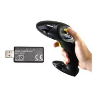
6.5.1.1 Measurement Tool Calibration
The calibration of the Measurement Tool is separated into two steps:
1. body calibration of the Measurement Tool and
2. calibration of the tip.
Body Calibration First, please calibrate the Measurement Tool with a standard body
calibration (see chapter 8.6.5.2 on page 177) by selecting Calibration → Body. In the up-
coming dialogue the body to be selected is named ’Measurement Tool body 01’. Please
define the orientation of the body coordinate system relative to the body (default setting
is due to body). Make sure that all markers of the Measurement Tool are seen by the
cameras using the Monitor 2DOF display which appears in the background.
If you are working with a reference body you would have to calibrate it as well. This is also
done by a standard body calibration. Just select the body named ’Measurement Tool ref-
erence body 01’.
Press "Calibrate" and the calibration starts within 5 seconds.
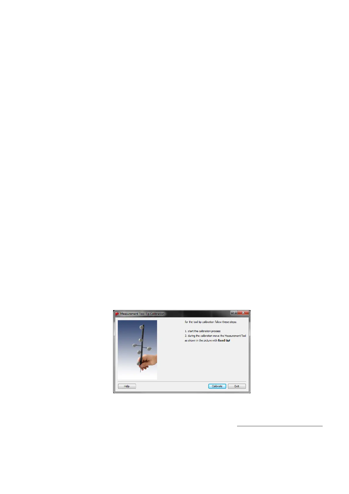
Tip calibration After a successful body calibration, you have to calibrate the tip of the
Measurement Tool by selecting Calibration → Measurement Tool (see figure 6.28 on
page 104) .
Figure 6.28: Measurement Tool Tip Calibration
Place the Measurement Tool in front of the cameras with the tip fixed at exactly one position
(e.g. on a hard surface). Press Calibrate to start the calibration process. Gently move
104