Chapter 8
8.6 Menu Calibration
Normal Powerwall
In the Normal setting the angle
defines the X/Y plane (X at the
long, Y at the short beam) and
Z upward.
With the Powerwall setting the
X/Y plane is in the screen and
the Z axis pointing out of the
screen. This is the standard
screen coordinate system of
many VR systems (e.g.
OpenGL, TrackD, etc.).
Table 8.17: Defining the coordinate system for the room calibration
is especially helpful for big systems.
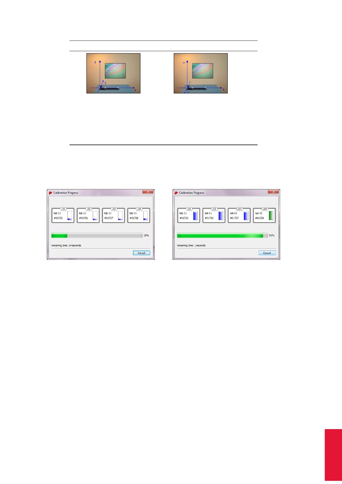
(a) (b)
Figure 8.24: Room calibration progress
As soon as the display for a camera changes its colour to green (see 8.24(b) on 169)
enough data for calculation of the camera position has been collected for this camera.
ARTTRACK5 only: This progress is also displayed individually on each the 2-digit LED
matrix display of each camera. After collection of sufficient data the LED matrix changes
back to its defined setting. Please refer to chapter 8.5.1 on page 146 for detailed informa-
tion.
Z
The point cloud should fill at least two thirds of the measurement vol-
ume. Moving the wand in restricted volume will results in reduced
accuracy of calibration or failure.
8.6.3.2 Room Calibration Results
After a successful room calibration, the DTrack2 info window with the calibration results is
displayed. This window shows the mean residuals for the single cameras (here: ’Resid-
ual’ = mean residual of rays during marker detection), as well as the mean deviation
169