8 DTrack2 frontend software
0.1
◦
on 5m length equals 8.7 mm deviation)
• shift and / or rotate the camera coordinate system to match a reference coordinate
system, e.g. from CAD models
• maintaining a specific coordinate system / orientation when using mobile installa-
tions of cameras, i.e. frequently changing the camera setup locations (suitable ref-
erence points provided)
In all these cases the coordinate system must be altered after calibration.
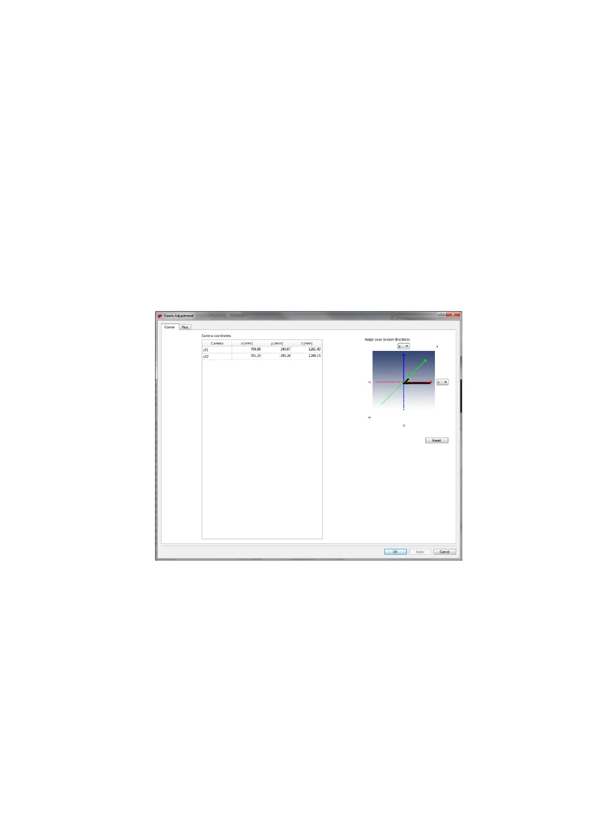
Coarse The Coarse tab offers a simple way to manipulate the orientation of the room
coordinate system with just one click (see figure 8.27 on page 172. You can define the
orientation of two axes using the drop-down menus - the third one will be oriented auto-
matically according to the right-hand rule.
Figure 8.27: Room adjustment dialogue (coarse)
Z
If you press Enter or click OK , all changes so far will be confirmed
(changes are sent to the controller) and the dialogue closes. Pressing
Apply accepts the current changes, but the dialogue is left open. Dis-
card all changes by pressing Cancel. Press Reset to switch back to
the unmodified state.
Fine More detailed options to adjust the room coordinate system are given in the Fine
tab (see figure 8.28 on page 173). By default a cartesian coordinate system is displayed
on the left side of the window. The room coordinate system is shown as a triplet of arrows
172