Appendix B
B.1 Definition of Coordinates and Rotations
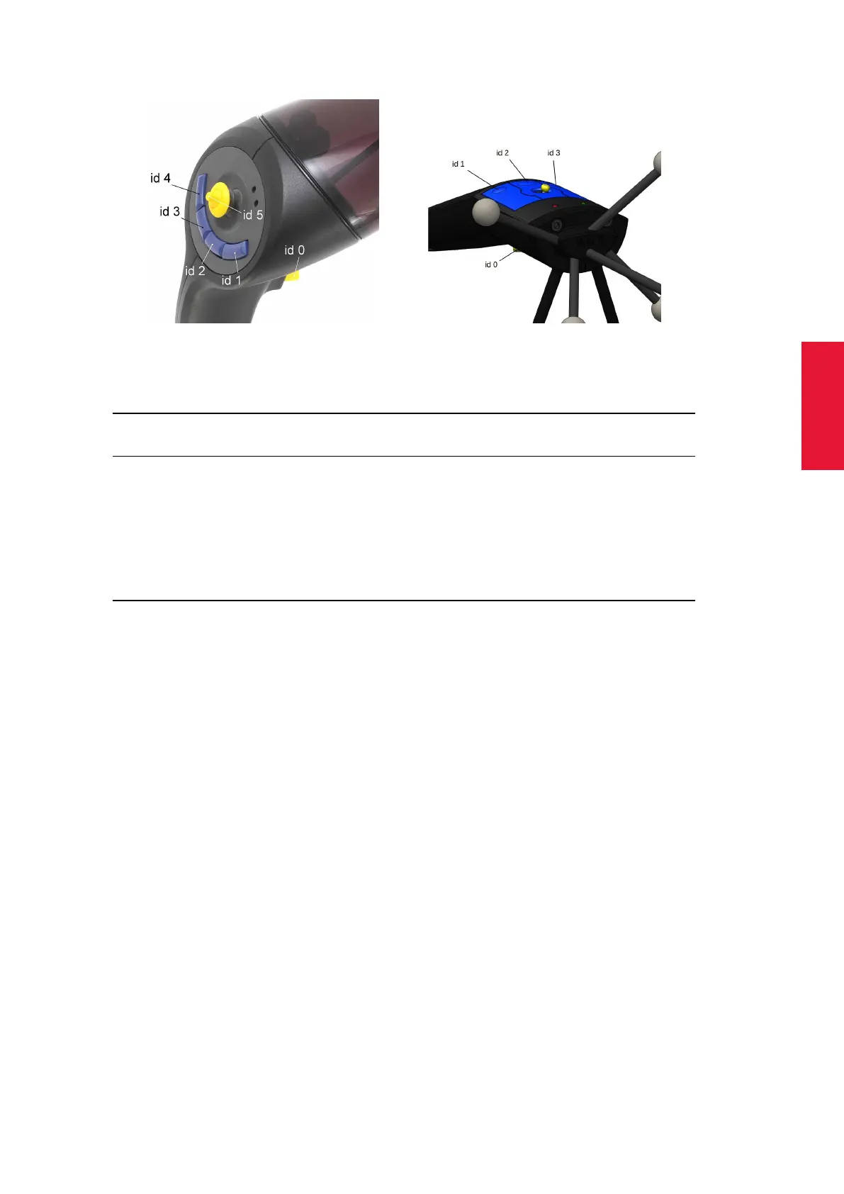
(a) Flystick2 (b) Flystick3
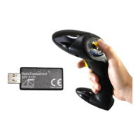
Figure B.1: Allocation of ID number to the Flystick buttons
Switch labelled as 6df Output 6df2 Output
(in figure B.1)
bottom switch (yellow) id 0 code 01 (hex) button code 01 (hex)
top right switch (blue) id 1 code 02 (hex) button code 02 (hex)
top middle switch (blue) id 2 code 04 (hex) button code 04 (hex)
top left switch (blue) id 3 code 08 (hex) button code 08 (hex)
joystick (yellow) to the left – code 20 (hex) first controller up to 1.0
joystick (yellow) to the right – code 80 (hex) first controller up to −1.0
joystick (yellow) up – code 40 (hex) second controller up to 1.0
joystick (yellow) down – code 10 (hex) second controller up to −1.0
B.1.6 Measurement Tools
i
Only available, if the Measurement Tool license is present for
DTrack2 (available since version v2.2.0)
The Measurement Tool license allows the use of Measurement Tools , i.e. pointing de-
vices with a special target geometry. While tracking, the module calculates position and
orientation of the tip of the tool. It is necessary to perform an additional calibration proce-
dure (called tip calibration) to provide the module with information about the tip.
B.1.6.1 Orientation of a Measurement Tool
The module modifies the local coordinate system (i.e. the body coordinate system) of the
tool’s body as follows:
1. The tip becomes the origin of the coordinate system.
2. The marker with the largest distance to the tip defines the +Z axis.
3. The marker, that is closest to the tip, defines the Y/Z plane.
This definition shall ease the use of the tip orientation. For instance, the orientation of all
ART Measurement Tools is approximately along the -Z axis.
255