Chapter 8
8.6 Menu Calibration
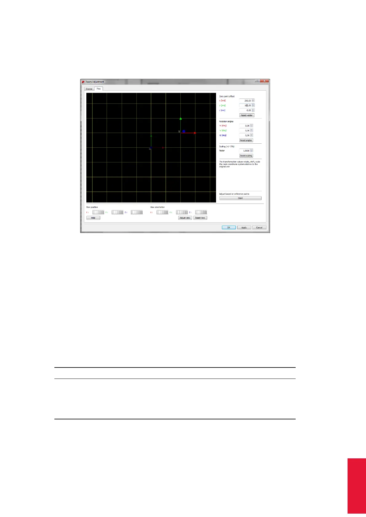
with a defined color-coding (x-axis: red, y-axis: green, z-axis: blue), while the xy-plane is
shown as a yellow grid. The current and the transformed room coordinate systems are
marked with (’O’) and (’T’) respectively.
Figure 8.28: Room adjustment dialogue (fine)
The View position and View orientation may be moved along and / or rotated around all
axes in two different ways:
1. hold down the "Ctrl" key and the left / right mouse button to change the position /
orientation
2. use the six control dials (below the graphical view) to adjust position and orientation
To center the current room coordinate system, press ’Adjust view’. To restore the default
view (shift and orientation), press ’Reset view’. The visualisation itself can be changed
by clicking the right mouse button to open a menu with the following options. (De-)select
the appropriate ones by (un-)ticking.
Option Description
’Long axes’ extends the coordinate axes of the body coordinate system by
infinite dashed lines
’Show XY plane’ shows the XY plane (yellow grid)
’Show YZ plane’ shows the YZ plane (cyan grid)
’Show XZ plane’ shows the XZ plane (magenta grid)
On the right side of the window the room coordinate system may be customized freely,
i.e. user-specific.
173