Protected by copyright. Copying for private or commercial purposes, in part or in whole, is not
permitted unless authorised by AUDI AG. AUDI AG does not guarantee or accept any liability
with respect to the correctness of information in this document. Copyright by AUDI AG.
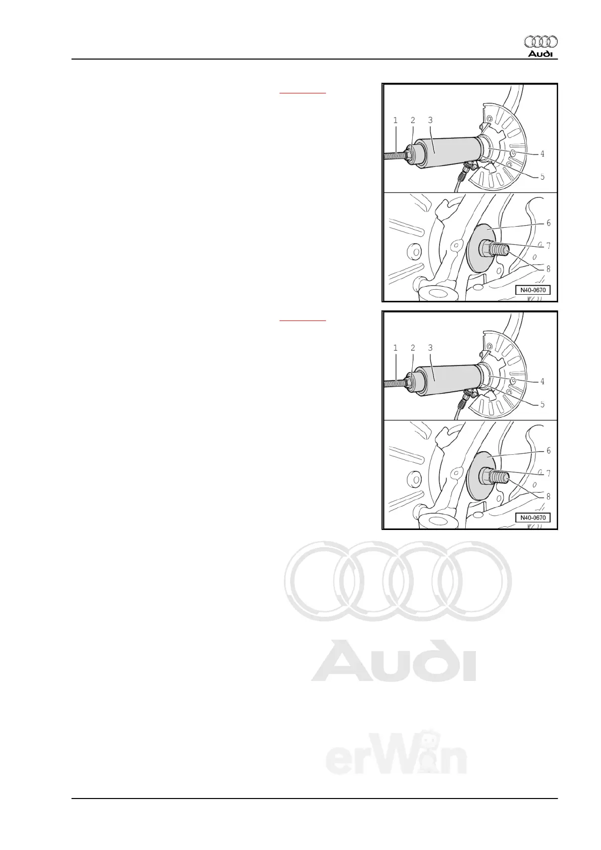
Versions with Dimension -x- = 83 mm, refer to ⇒ page 83
– Mount tools as depicted in illustration.
1 - Threaded Rod M20 - T10205/8-1-
2 - M20 Nut - T10205/8-2-
3 - Hydraulic Press - VAS6178-
4 - Wheel Bearing
5 - Thrust Piece - T10205/7-
6 - Thrust piece - T10205/9- , the collar must face the wheel
bearing housing.
7 - M20 Nut - T10205/8-2-
8 - Threaded Rod M20 - T10205/8-1-
Versions with Dimension -x- = 75 mm, refer to ⇒ page 83
– Mount tools as depicted in illustration.
1 - Threaded Rod M20 - T10205/8-1-
2 - M20 Nut - T10205/8-2-
3 - Hydraulic Press - VAS6178- with Pressure Head -
T10205/13-
4 - Wheel Bearing
5 - Thrust Piece - T10205/7-
6 - Thrust Piece - T40185/4-
7 - M20 Nut - T10205/8-2-
8 - Threaded Rod M20 - T10205/8-1-
Continuation for both variants
– Connect Pneumatic/Hydraulic Foot Pump - Pressure Gauge -
VAS6179/1- between Hydraulic Press - VAS6178- and hy‐
draulic line of Hydraulic Press - VAS6178- .
Pressures, described in the following, apply only to the Hydraulic
Press - VAS6178- .
While pressing in, pressure reading must be between 100 and
190 bar shortly before end of pressing in.
Maximum pressure must not exceed 310 bar.
– Press wheel bearing in until stop.
– Install circlip.
Audi Q7 2007 ➤
Suspension, Wheels, Steering - Edition 01.2014
5. Lower Control Arm, Wheel Bearing Housing, Wheel Hub and Wheel Bearing 97

 Loading...