Protected by copyright. Copying for private or commercial purposes, in part or in whole, is not
permitted unless authorised by AUDI AG. AUDI AG does not guarantee or accept any liability
with respect to the correctness of information in this document. Copyright by AUDI AG.
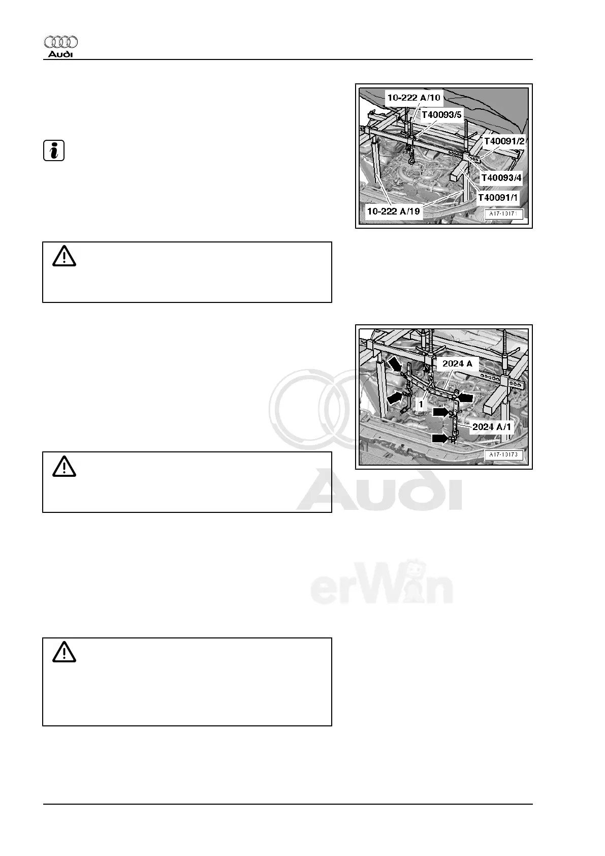
– Install additional Engine Support Bridge - 10-222A- parts as
shown in illustration. Also place Engine Support Bridge - En‐
gine Support 19 - 10-222A/19- on notches on longitudinal
members.
Note
Mount the Engine Support Bridge - Engine Support 19 - 10-222A/
19- to the notches on the longitudinal member. Push the left re‐
frigerant lines to the side and out of the way.
– Slide Support - T40091/2- with Slides - T40093/5- into both
Mounts - T40093/4- .
WARNING
Secure Support - T40091/2- with connector pins and Mounts -
T40093/4- .
– Remove Engine Sling - 2024A- eyes.
– Insert pins -1- in center Engine Sling eye and secure with a
splint.
– Engage engine sling pins at front engine support bridge spin‐
dle.
– Install Engine Sling - Engine Bracket - 2024A/1- on left side of
engine sling.
– Engage Engine Sling - 2024A- at front right engine lifting eye
and at Engine Support - T10014- .
WARNING
Hooks and pins on engine sling must be securing with con‐
nectors -arrows-.
– Tension engine by tightening 3 spindles evenly.
Affects all Vehicles
– Remove both brackets with ABS speed sensor and brake wear
indicator electrical lines at wheel bearing housing and discon‐
nect connectors.
– Remove brake caliper and secure to body so that weight of
caliper does not stress or damage brake hose or brake line.⇒
Rep. Gr. 46
Caution
• The Hose Clamps - Up To 25mm - 3094- must not be se‐
cured on return hose in check valve area.
• The check valve is in the return hose between the cambers
-A arrows- or between hose clamps -B arrows-.
Audi Q7 2007 ➤
Suspension, Wheels, Steering - Edition 01.2014
24 Rep. Gr.40 - Front Suspension