Design and Operation
Instruction handbook bmaXX 5000
Document No.: 5.09021.19
101
of 346
4
4.4.3 Display and operating elements BM53XX
Figure 43: Display/operating elements controller BM53XX
X1 Service interface
H1
H2
7 segment display axis 1
7 segment display axis 2 (double axis unit)
Display controller state
Meaning refer to: Z7-segment display controller– on page 102
LED
H11 - H14
H21 - H24
LED axis 1
LED axis 2 (double axis unit)
Meaning: refer to ZLED display controller– on page 103.
Address switch
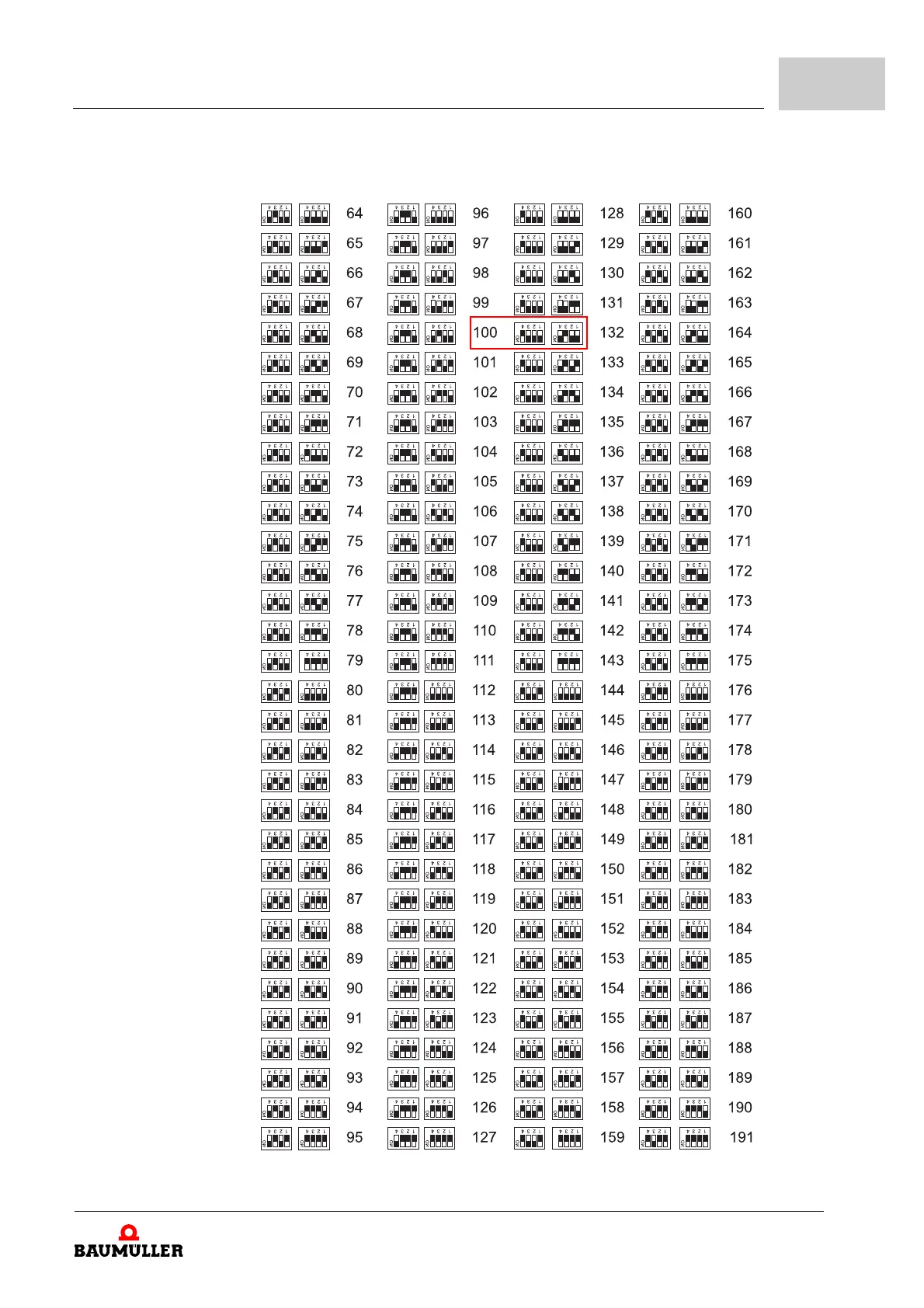
S1 - S4 Setting: refer to ZSetting the IP address with address
switches– as from page 106.
LED
H31
H32
H41
H42
Fieldbus, depending on type
(refer to ZType code– as from page 90)
Meaning:
BM53XX-XXXX-XXXX-01XX
BM53XX-XXXX-XXXX-07XX
ZLED EtherCAT
®
.– on page 104
BM53XX-XXXX-XXXX-02XX
ZLED VARAN– on page 104
BM53XX-XXXX-XXXX-04XX
ZLED POWERLINK
®
.– on page 105
NOTE!
Only the service cable BM5-K-USB-XXX is allowed to be used for the service inter-
face X1, refer to ZService interface– on page 219 and ZService interface cable– on
page 266.