Uni-Probe LB 490
BERTHOLD TECHNOLOGIES GmbH & Co. KG
2 – 153
Volume 2 2 Installation
2
foils on the modules, since you have to check the accuracy of fit
first.
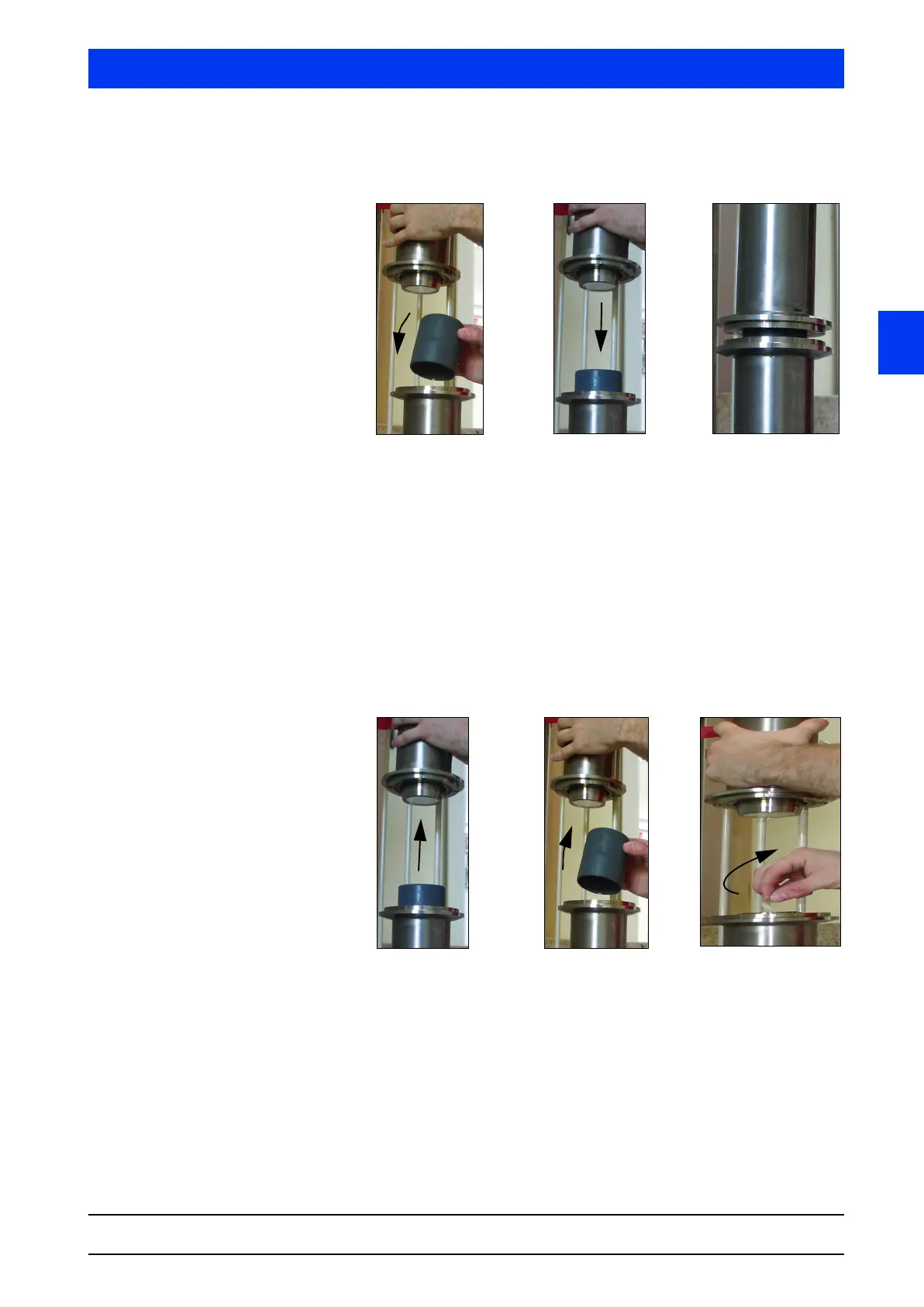
Figure 2-7 Aligning an extension module
Place the guide sleeve on the basic module (Figure 2-7a).
Open the fixing clamp of the extension module, push the exten-
sion module into the guide sleeve and carefully push the mod-
ule down until you reach the basic module (Figure 2-7b and c).
This must be possible without encountering any resistance,
otherwise the fixing clamps are not aligned correctly and have
to be re-adjusted. For adjusting, remove the extension module
again and place the protective caps onto the modules.
Pull the extension module up again by approx. 20cm and
secure it with the fixing clamp (Figure 2-8d).
Figure 2-8 Aligning an extension module
Remove the guide sleeve from the basic module (Figure 2-8e).
Pull off the protective foils from the basic module and on the
bottom of the extension module (Figure 2-8f).
Place the guide sleeve on the basic module (Figure 2-9g).
 Loading...
