38477BA2B
2 – 162 25.5.09
2 Installation Volume 2
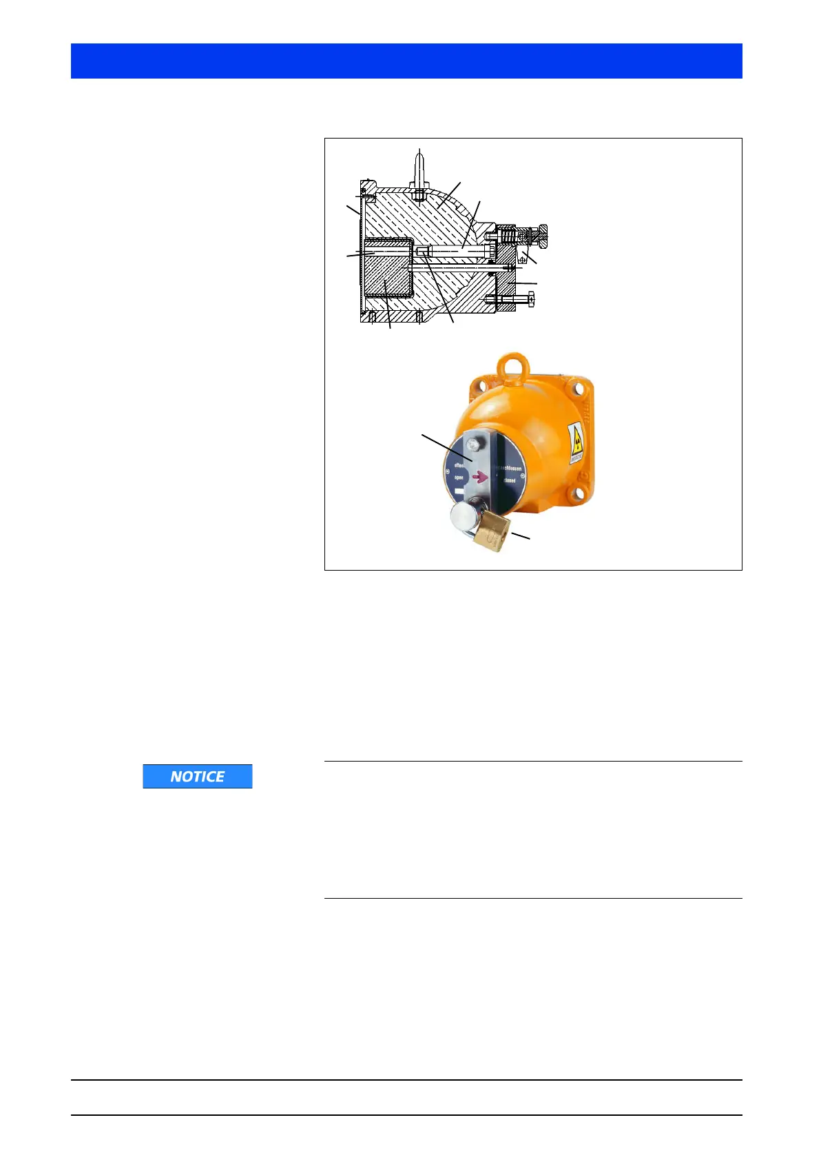
Figure 2-20 Cross-section drawing and photo of the point source shielding,
beam path open
Turning the lever (4) will also rotate the locking core and open the
radiation exit channel towards the detector. The arrow on the lever
is pointing to OPEN.
The radiation exit channel must be closed during transportation,
during installation and while carrying out work on the vessel. The
arrow on the lever is pointing to CLOSED. In the OPEN and CLOSED
position, the lever or the locking core are protected by a padlock.
Function failure due to damage
The detector fixture must not transfer any vibrations or heat onto
the shielding; otherwise the locking mechanism may be damaged
and the shielding effectiveness may be adversely affected.
Therefore, install the fixture on a vibration-free support or attenu-
ate possible vibrations using vibration absorbers. Prevent heat
transfer by using suitable insulating materials.
Installing the Shielding The shielding can either be installed on a bracket or on a flange,
see "6.5.1 Installation Proposal for Point Source Shielding LB
744X", page 2–274. The size and position of the measurement
range to be covered are determined in the projection phase of the
measuring system and defined in drawings, sketches or details in
1
1 Shielding
2 Source fixture
3Padlock
4 Locking bolt
5 Point sources
6 Locking core
7 Beam path
8 Cover plate, front
2
3
4
5
6
7
8
3
4
 Loading...
