38477BA2B
2 – 164 25.5.09
2 Installation Volume 2
Function failure due to damage
The detector fixture must not transfer any vibrations or heat onto
the shielding; otherwise the locking mechanism may be damaged
and the shielding effectiveness may be adversely affected.
Therefore, install the fixture on a vibration-free support or attenu-
ate possible vibrations using vibration absorbers. Prevent heat
transfer by using suitable insulating materials.
Install shielding 45°
Before installing the source shielding or the source, you have to
determine the background for rod detectors (see Volume 3, section
4.3.1 on page 3–351).
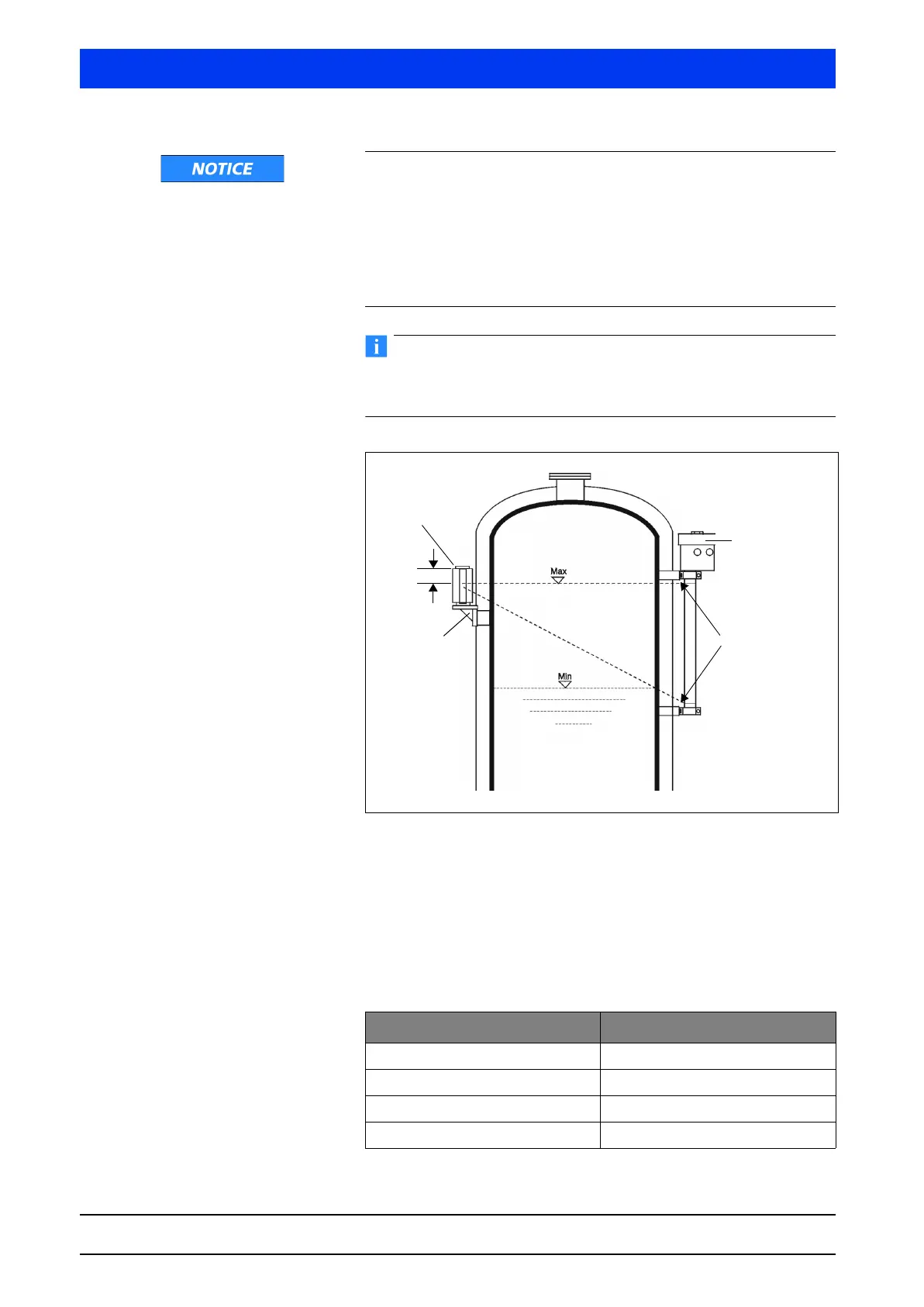
Figure 2-23 Point source with rod detector
The standard arrangement (Figure 2-23) shows the mounting posi-
tion of the shielding with point source; G indicates the topmost
point of the measuring range that can be covered. The shielding
must be mounted on a suitable fixture provided by the customer in
the appropriate height, so that the upper edge of the shielding is
positioned above the measuring range offset by “G”.
Size G for various shielding types
Shielding type Size G (in mm)
100 115
150 115
200 155
270 200
Uni-Probe LB 490
Point source
shielding
Mounting
bracket
Marking groove
G