Uni-Probe LB 490
BERTHOLD TECHNOLOGIES GmbH & Co. KG
2 – 165
Volume 2 2 Installation
2
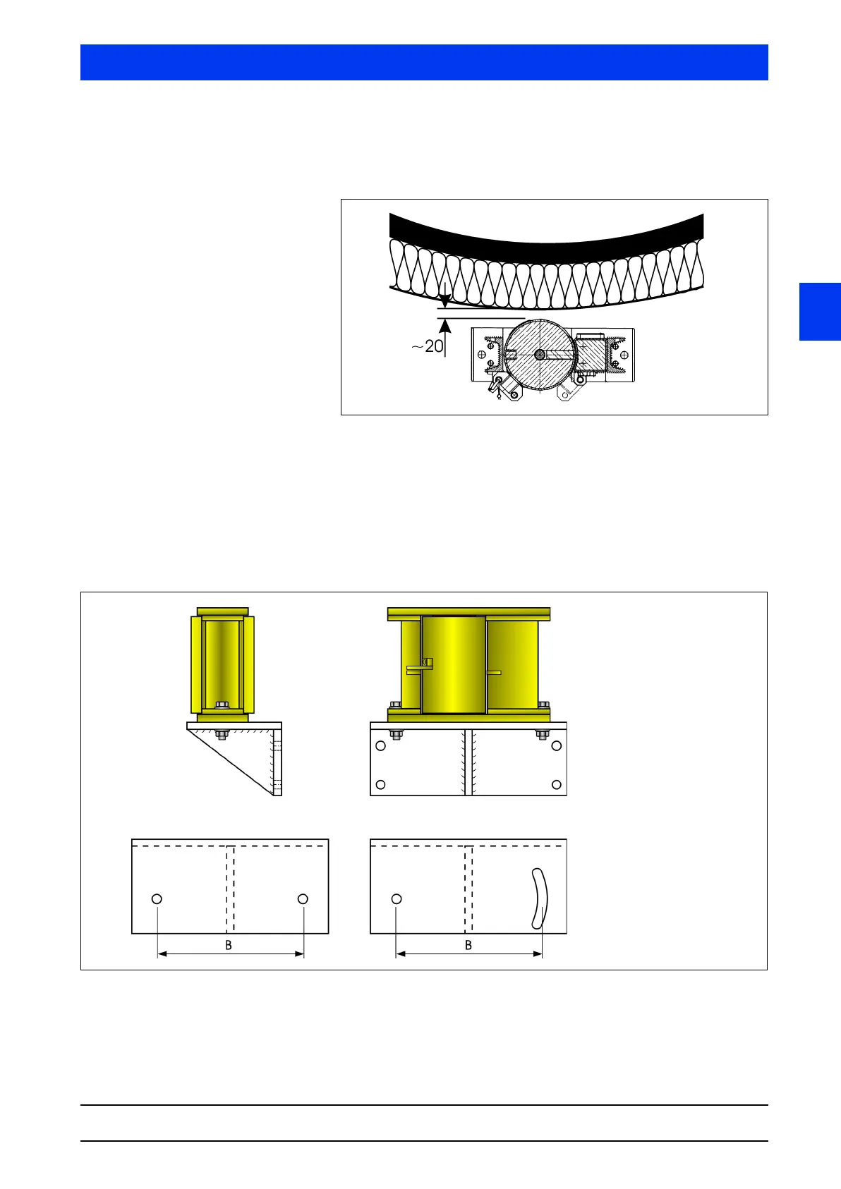
The distance from the source shieldings to the vessel surface is
designed such that reaching into the beam path with the hand is
prevented (reference value approx. 20mm).
Figure 2-24 Distance of the source shielding from the vessel surface
The dimensional drawings show the size of the different shieldings,
see section 6.5on page 2–273.
Figure 2-25 shows a proposal for a mounting bracket for the source
shielding. The size and rigidity of the mounting bracket has to
match the size and weight of the shielding. The bracket has to be
mounted in the appropriate height, if possible, directly on the ves-
sel or via an external supporting structure.
Figure 2-25 Installation proposal shielding; size B see section 6.6 on
page 2–281
Shielding 45°
with point source
Mounting base 1
This version is easier to
make than version 2
Mounting base 2
The version of the mounting
base with an elongated hole
allows the alignment of the
source at the detector