261
Powerhead
Powerhead Assembly
11
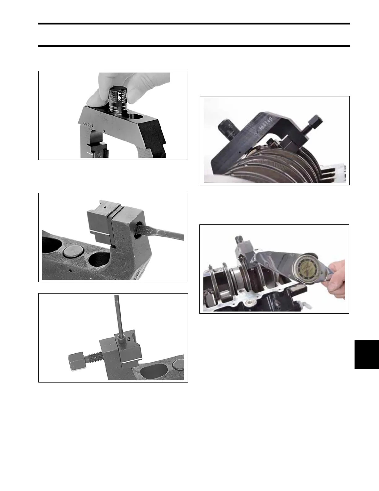
est setting (two lines showing). Rotate adjustment
knob 180° to lock the stop in position.
Secure restraining jaw “A” and forcing jaw “B” to
frame.
Apply a light coat of outboard lubricant to the cor-
ners of the connecting rod and rod cap. Place
frame on connecting rod using the following pro-
cedure:
• Position frame onto the connecting rod so the
contact area of the jaw is centered on the side
of the rod.
• Tighten forcing screw until jaws contact con-
necting rod.
• Slide frame down until adjustment stop contacts
the rod cap. The groove lines on the jaws must
be centered on the rod/crankpin diameter.
• Tighten the forcing screw to a torque of 23 in.
lbs. (2.5 N·m).
IMPORTANT: Make sure that frame is squarely
in position and that rod and cap are aligned.
Loosen both rod cap screws one-quarter turn.
Use Torquing Socket, P/N 346187, to tighten rod
cap screws in three stages:
• Apply first torque of 40 to 60 in. lbs. (5 to 7 N·m)
to both rod cap screws.
• Tighten screws to a torque of 20 to 22 ft. lbs. (27
to 30 N·m).
1. Adjustment stop, highest setting
2287
Restraining Jaw “A”
21591
Forcing Jaw “B”
21594
1. Adjustment stop
2. Groove line
21589
009705