5
5
5-11
5-11
Troubleshooting > Connector Layout Drawing
Troubleshooting > Connector Layout Drawing
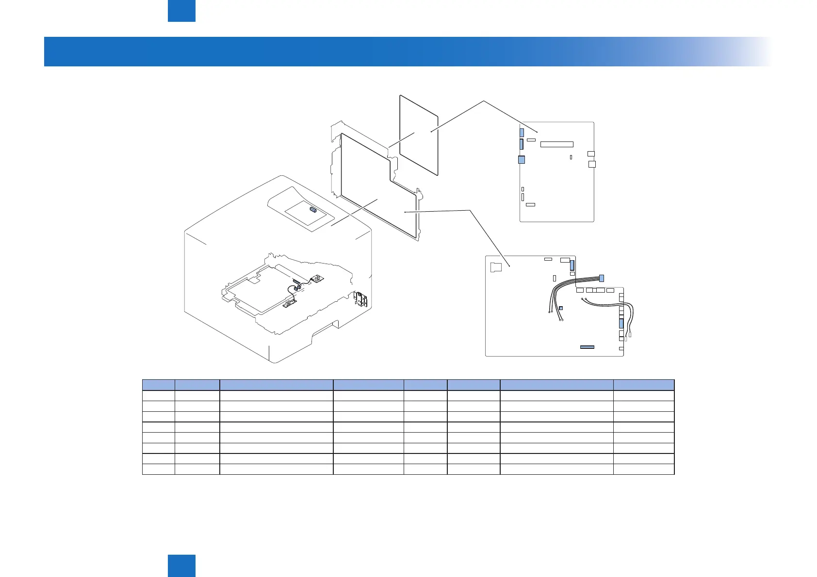
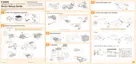
Connector Layout Drawing
■
Connectors Layout Drawing (LBP3560/6750dn) (1/3)
J501
J507
J513
J1301
Main Controller PCB
J201
J1701
J1302
J2
J1801
J1610
J3
J1
J2
Engine Controller
PCB
J No. Symbol Name Relay connector J No. Symbol Name Remarks
J1701 - Engine Controller PCB J1 - Main Controller PCB
J2 - Engine Controller PCB J2 - Main Controller PCB
J1302 - Engine Controller PCB J1301 SW1301 Power Switch
J1801 - Engine Controller PCB J8007 J401 - Paper Feeder Relay PCB
J1610 - Engine Controller PCB J501 - High Voltage Power Supply Unit
J3 - Main Controller PCB J201 - Control Panel PCB
J513 - High Voltage Power Supply Unit J513 PS225 Paper Width Sensor
J507 - High Voltage Power Supply Unit J507 PS215 Top Sensor
F-5-24
T-5-22