3
3
3-35
3-35
Disassembly/Assembly > Controller System > Removing the Engine Controller PCB (LBP3560/6750dn) > Procedure
Disassembly/Assembly > Controller System > Removing the Engine Controller PCB (LBP3560/6750dn) > Procedure
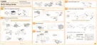
3) Shift the host machine 50 mm to the right.
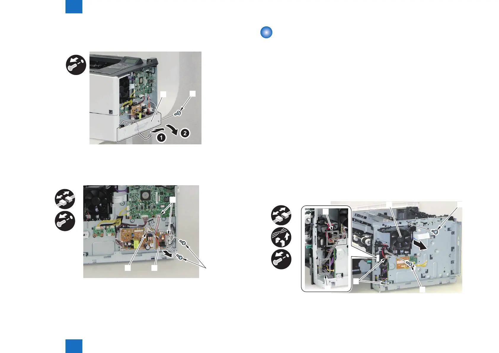
4) Remove the Right Lower Cover [1].
• 1 Screw (black) [2]
[2]
[1]
5) Place the host machine in the center of working table.
6) Remove the AC Relay PCB [1].
• 3 Connectors [2]
• 2 W Sems Screws [3]
x2
x3
[1]
[2]
[3]
[2]
F-3-68
F-3-69
Removing the Engine Controller PCB
(LBP3560/6750dn)
■
Preparation
1) Remove the Multi-purpose Tray Auxiliary Tray Unit.(Refer to page 3-20)
2) Remove the Right Cover.(Refer to page 3-17)
3) Remove the Right Front Inner Cover.(Refer to page 3-21)
4) Remove the Right Lower Cover.(LBP3560/6750dn)(Refer to page 3-22)
5) Remove the Main Controller PCB.(LBP3560/6750dn)(Refer to page 3-30)
6) Remove the Control Panel Unit.(LBP3560/6750dn)(Refer to page 3-28)
7) Remove the Upper Cover.(Refer to page 3-25)
8) Remove the Rear Cover Unit.(Refer to page 3-19)
9) Remove the Rear Right Cover.(Refer to page 3-19)
■
Procedure
1) Remove the Main Fan Unit [1].
• 2 Connectors [2]
• Harness Guide [A]
• Harness Guide [B]
• 1 Screw (TP) [3]
• 1 Screw (tapping) [4]
x2
x2
x2
[4]
[2]
[B]
[A]
F-3-70