2
2
2-4
2-4
Technology > Laser Exposure System > Optical Unit Failure Detection
Technology > Laser Exposure System > Optical Unit Failure Detection
Laser Exposure System
Outline
The laser exposure system forms a latent image on the photosensitive drum according to the
VIDEO signalssent from the Main Controller.
The main components of the laser scanner are the laser unit and the scanner motor unit,
which arecontrolled by the signals sent from the DC controller.
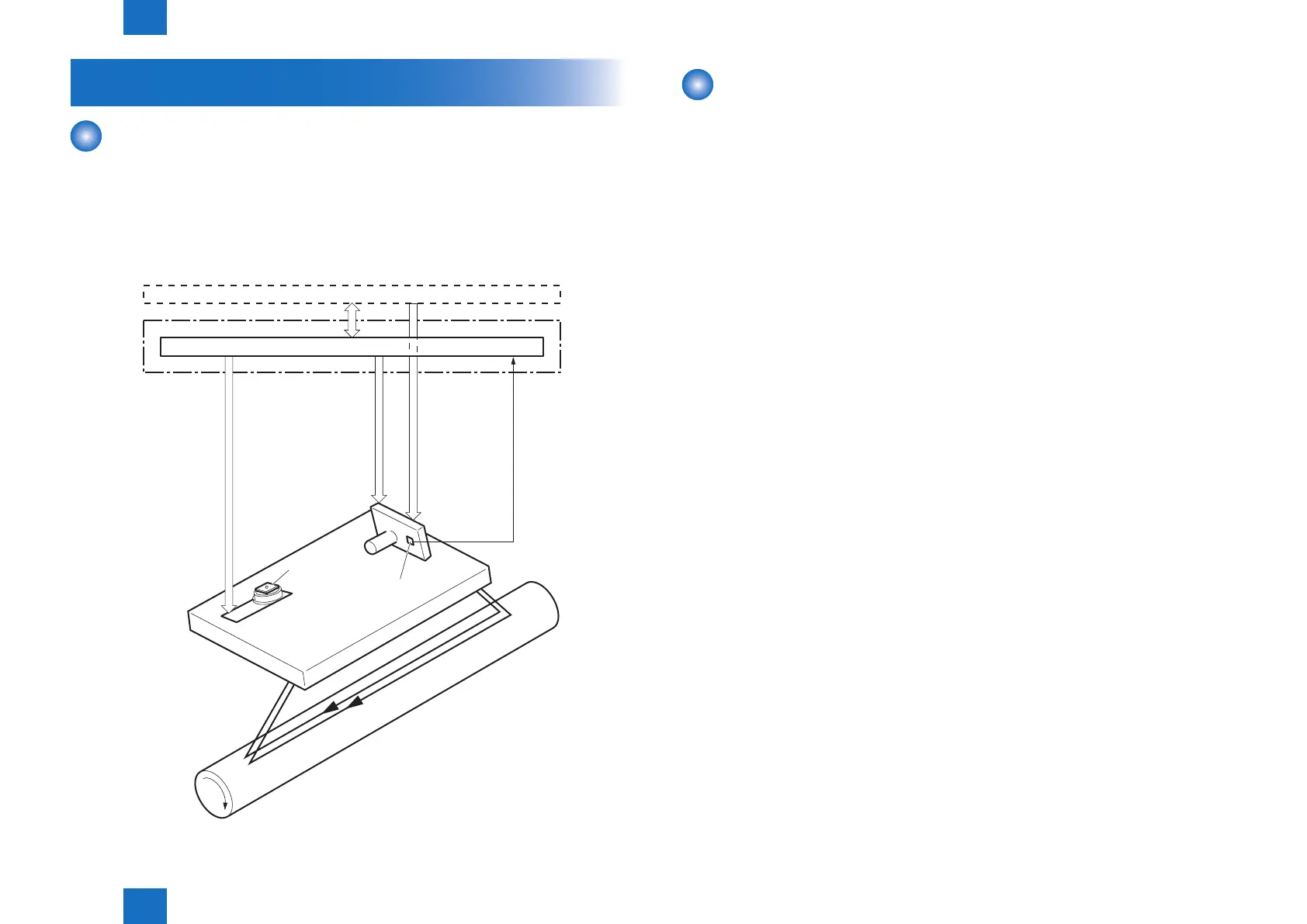
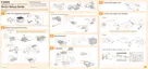
Diagram of the Laser Scanner Unit is shown below.
Main contoroller
DC controller
Photosensitive drum
Scanning mirror
BD sensor
Laser unit
Scanner motor unit
BDI signal
VIDEO signal
LASER CONTROL signal
SCANNER MOTOR CONTROL signal
Engine controller
F-2-2
Optical Unit Failure Detection
The optical unit failure detection manages the laser scanner failure detection functions.
The DC controller determines an optical unit failure and noties E100 to the Main controller if
the laser scanner encounters the following conditions:
• If the scanner motor does not reach a specied rotation within a specied period of start-up.
• If the rotation of the scanner motor is out of specied range for a specied period during
drive.
• If an out of specied BD interval is detected during a print operation.