3
3
3-37
3-37
Disassembly/Assembly > Controller System > Removing the Engine Controller PCB (LBP3580/6780x) > Procedure
Disassembly/Assembly > Controller System > Removing the Engine Controller PCB (LBP3580/6780x) > Procedure
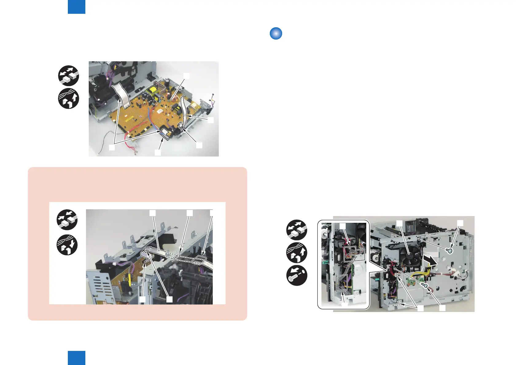
6) Remove the Engine Controller PCB [1].
• 3 Flat Cables [2]
• 1 Harness Guide [A]
• 1 Harness Guide [B]
[1]
[2]
[2]
[A]
[B]
x3
x2
CAUTION:
When installing the Laser Scanner Flat Cable [1], be sure to install it to the connector [2],
Guide [3], hole [4] on the Right Side Plate, and Ferrite Core [5], in that order.
[1]
[2] [3]
[4] [5]
F-3-76
F-3-75
Removing the Engine Controller PCB
(LBP3580/6780x)
■
Preparation
1) Remove the Multi-purpose Tray Auxiliary Tray Unit.(Refer to page 3-20)
2) Remove the Right Cover.(Refer to page 3-17)
3) Remove the Right Front Inner Cover.(Refer to page 3-21)
4) Remove the Right Lower Cover.(LBP3580/6780x)(Refer to page 3-22)
5) Remove the Main Controller PCB.(LBP3580/6780x)(Refer to page 3-30)
6) Remove the USB Cover Unit.(LBP3580/6780x)(Refer to page 3-24)
7) Remove the Control Panel Unit.(LBP3580/6780x)(Refer to page 3-28)
8) Remove the Upper Cover.(Refer to page 3-25)
9) Remove the Rear Cover Unit.(Refer to page 3-19)
10) Remove the Rear Right Cover.(Refer to page 3-19)
■
Procedure
1) Remove the Main Fan Unit [1].
• 2 Connectors [2]
• Harness Guide [A]
• Harness Guide [B]
• 1 Screw (TP) [3]
• 1 Screw (tapping) [4]
x2
x2
x2
[2]
[1]
[B]
[A]
[3]
[4]
F-3-77
 Loading...