DETAILED STEPS
Step 1
At the front of the router, ensure that the power switch is in the Standby position.
Step 2
Move the circuit-breaker switch handle to the Off position, and apply tape to hold it in the Off position.
Step 3
Gather the DC power supply terminal block plug.
Step 4
Insert the lead wires before inserting the plug into the terminal block header on the DC power supply.
Step 5
Use a 10 gauge wire-stripping tool to strip each of the three wires coming from the DC input power source. If you are
using the connector plug with the raised screw holes, strip the wires to 0.39 inch (10 mm) + 0.02 inch (0.5 mm). If you
are using the connector plug with the screw holes that are not raised, strip the wires to 0.27 inch (7 mm) + 0.02 inch (0.5
mm). Do not strip more than the recommended length of wire because doing so could leave the wire exposed from the
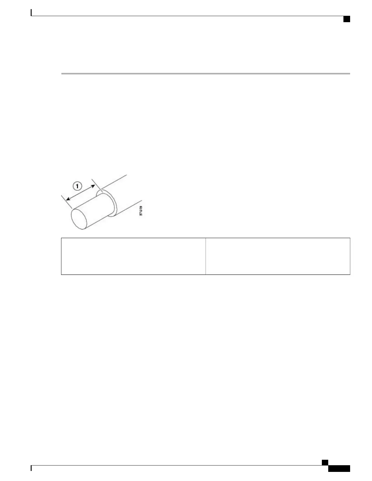
terminal block plug. The following figure shows a stripped DC input power source wire.
Figure 222: Stripping the DC Input Power Source Wire
0.39 inch (10 mm) is the recommended wire-strip length
for the connector plug that has raised screw holes. 0.27
inch (7 mm) is the recommended wire-strip length for the
connector plug that does not have raised screw holes.
1
An exposed wire lead from a DC input power source can conduct harmful levels of electricity. Be sure that
no exposed portion of the DC input power source wire extends from the terminal block plug. Statement 122
Danger
Step 6
Identify the positive, negative, and ground feed positions for the terminal block connection. The recommended wiring
sequence is:
•
Ground lead wire (right)
•
Positive (+) lead wire (middle)
• Negative (–) lead wire (left)
Cisco ASR 1000 Series Router Hardware Installation Guide
455
Cisco ASR 1001 Router Overview and Installation
Installing DC Input Power on the Cisco ASR 1001 Router
 Loading...


