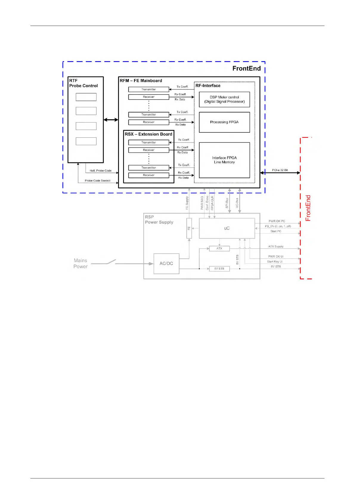
5.2 FrontEnd Processor
Figure 5-5 FrontEnd - Block diagram
Content in this section
5.2.1 RTF - Probe Control Board - - - - - - - - - - - - - - - - - - - - - - - - - - - - - - - - - - - - - - - - 5-24
5.2.2 RSE - Pencil Probe Board (optional) - - - - - - - - - - - - - - - - - - - - - - - - - - - - - - - - - 5-24
5.2.3 RFM - (RF-Interface & Beamformer) FE Mainboard - - - - - - - - - - - - - - - - - - - - - - 5-24
5.2.4 RSX - (Beamformer Receiver/Transmitter) Extension Board - - - - - - - - - - - - - - - - 5-24
Components and Functions (Theory)
Voluson E-Series Service Manual
5539550APB Revision 6
5-23