5.5 Control Console (User Interface)
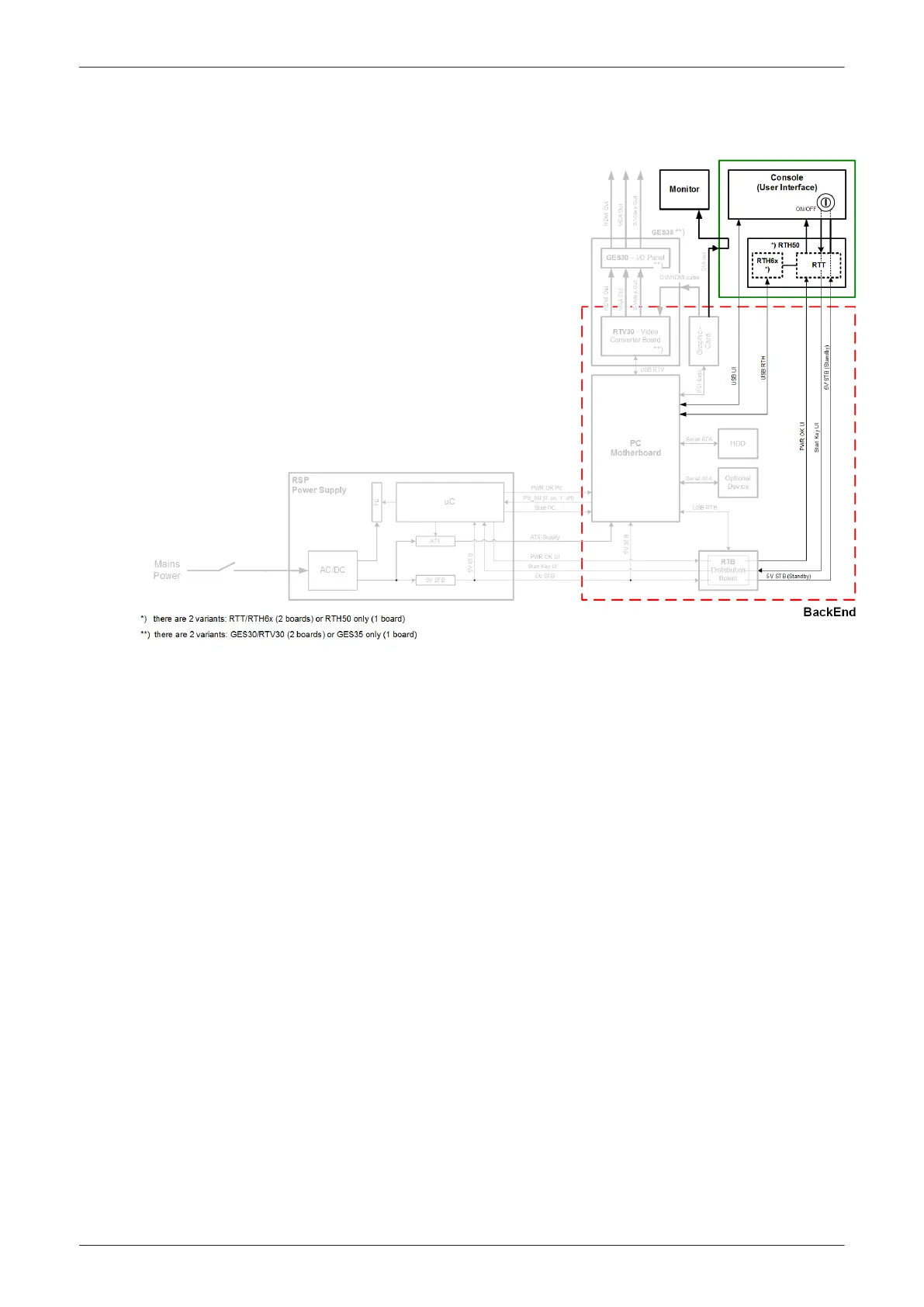
Figure 5-14 Control Console (User Interface) - Block diagram
The Voluson E-Series control console (User Interface) consists of the following electronic sub-assemblies
and/or functional components:
•
Display/Touch screen module:
-
WXGA display - 1280 x 800 pixels
-
Integrated USB to Video converter with USB2.0 High Speed Interface
-
projected capacitive touch screen
•
Console module:
-
7 port USB 2.0 Hub controller
-
Contols (Encoder/Joycoder) with integrated rotary/push/flip function
-
USB Trackball (2”) with dedicated buttons to emulate standard three button mouse
-
USB standard alphanumeric keyboard
-
USB extended keyboard with controller
-
LED Indicators with wide range dimming
-
LED to illuminate probe port connectors
•
DC/DC Converter:
-
Converts 12VDC input voltage to 5VDC and 3.3VDC output voltage for supplying User Interface
components
Components and Functions (Theory)
Voluson E-Series Service Manual
5539550APB Revision 6
5-35